Stylus Photo R300/R310 | Revision A |
2.3.12 Removing Print Head
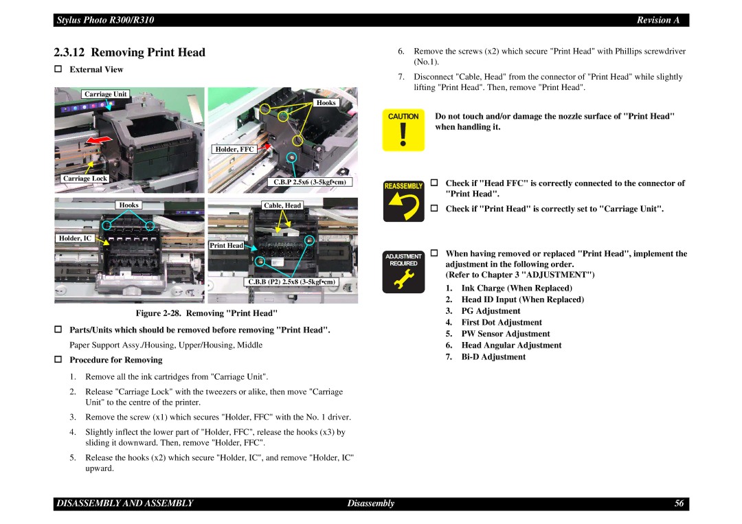
External View
6.Remove the screws (x2) which secure "Print Head" with Phillips screwdriver (No.1).
7.Disconnect "Cable, Head" from the connector of "Print Head" while slightly lifting "Print Head". Then, remove "Print Head".
Carriage Unit
Carriage Lock
Hooks
Holder, IC ![]()
Hooks
Holder, FFC ![]()
![]()
C.B.P 2.5x6
Cable, Head
Print Head
CAUTION Do not touch and/or damage the nozzle surface of "Print Head" when handling it.
Check if "Head FFC" is correctly connected to the connector of "Print Head".
Check if "Print Head" is correctly set to "Carriage Unit".
C.B.B (P2) 2.5x8
ADJUSTMENT
REQUIRED
When having removed or replaced "Print Head", implement the adjustment in the following order.
(Refer to Chapter 3 "ADJUSTMENT")
1. | Ink Charge (When Replaced) |
2. | Head ID Input (When Replaced) |
Figure 2-28. Removing "Print Head"
Parts/Units which should be removed before removing "Print Head". Paper Support Assy./Housing, Upper/Housing, Middle
Procedure for Removing
1.Remove all the ink cartridges from "Carriage Unit".
2.Release "Carriage Lock" with the tweezers or alike, then move "Carriage Unit" to the centre of the printer.
3.Remove the screw (x1) which secures "Holder, FFC" with the No. 1 driver.
4.Slightly inflect the lower part of "Holder, FFC", release the hooks (x3) by sliding it downward. Then, remove "Holder, FFC".
5.Release the hooks (x2) which secure "Holder, IC", and remove "Holder, IC" upward.
3. | PG Adjustment |
4. | First Dot Adjustment |
5. | PW Sensor Adjustment |
6. | Head Angular Adjustment |
7. |
DISASSEMBLY AND ASSEMBLY | Disassembly | 56 |