Epson Stylus Photo R300/R310
Page
Precautions
About This Manual
Revision Status
Contents
Troubleshooting
Sensor check point
Troubleshooting Flowchart Motor, Coil Resistance
LED/LCD Indication and STM3
Reaches about 90%
Data error
Troubleshooting
This error is detected when CD/DVD Tray
Check Points for Communication Error to Each Phenomenon
Unit Level Troubleshooting
Check Points for Paper Out Error to Each Phenomenon
Is ejected without being set at the print Start position
Lever, Change
Check Points for Paper Jam Error to Each Phenomenon
Occurrence Phenomenon Detail Faulty Part Check Point Remedy
Paper Guide, Upper
Check Points for CD/DVD Guide Error to Each Phenomenon
CDR/DVDR
Check Points for CD/DVD Tray Error to Each Phenomenon
10. Check points for Memory Card Error to Each Phenomenon
11. Check Points for Fatal Error to Each Phenomenon
13. Check Points for Abnormal Sound
14. Check Points for Defective Print Quality
Refer to Section
At operation
LD Roller
With a soft cloth
Disassembly and Assembly
Precautions
Tools
Service Completion Pre-Shipment Check List
Pre-Shipment Checks
Tools
Disassembly and Assembly
† Caution for disassembly/assembly of Printer Mechanism
† How to secure the quality for reassembled products
Disassembly
† External View
Removing Paper Support Assy
Removing Housing, Upper
Removing Housing, Upper
Reinstalling Printer Cover
Paper Support Assy./Housing, Upper
Removing Housing, Middle
Mounting Panel FFC
Vertical Direction 4 ± 1mm Horizontal Direction 1-2mm
Removing Porous Pad, Paper Guide, Front
Removing Panel Board
Removing Stacker Assy
14. Reinstalling Stacker Assy
Removing Main Board
Connectors connected to C536 Main Board
„ Make sure to match Panel FFC and the lateral face
Shield Plate, M/B and then attach it to Main Board
Assy. with a two-sided tape
Adjustment † Required
18. Removing ASF Assy
Removing ASF Assy
Torsion Spring
20. Removing Holder, Shaft Assy
Removing Holder, Shaft Assy
„ Removing LD Roller
† Reinstalling LD Roller
LD Roller
Removing CR Motor
26. Removing APG Assy
Removing APG Assy
Removing Print Head
PG Adjustment
29. Removing Carriage Unit
Removing Carriage Unit
30. Removing Carriage Unit
„ Removing CR Encoder Sensor Board
„ Removing Pulley, Driven
„ Removing Csic Board
„ Removing PW Sensor Board
Slider, Holder, Scale
Adjustment † Required
Upper
Removing Paper Guide, Upper
38. Removing Printer Mechanism/Housing, Lower
Removing Printer Mechanism/ Housing, Lower
† When lifting up Printer Mechanism, Lever, Change
Combination Gear, 27.2, 19.2 may detach and drop. Take care
Not to drop and damage them
42. Installing Waste Ink Pads
Left
Removing Power Supply Unit
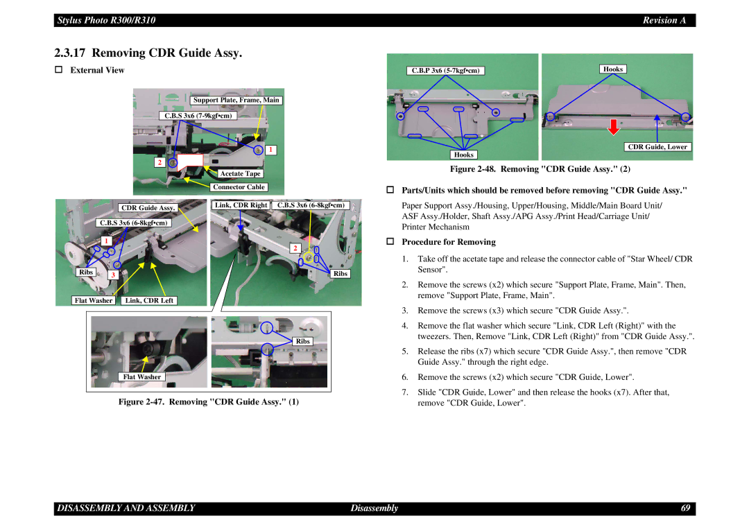
47. Removing CDR Guide Assy
Removing CDR Guide Assy
49. Removing CDR Guide Assy
Removing Ink System
† External View † Procedure for Removing
† Do not remove the ink tube which is connected to Cap Assy
Pump Assy
52. Connecting Point for the ink tube
Disassembly and Assembly
Transform Star Wheels of Frame EJ Assy
Removing Paper Guide, Front/Roller EJ Assy
55. Removing Paper Guide, Front/Roller EJ Assy
56. Removing Paper Guide, Front/Roller EJ Assy
Adequate dose to the specified points
Removing PF Motor
Adjustment
Adjustment Items
Servicing Adjustment Item List
Function Item Purpose Adjustment Outline Tool Used Media
Maintenance Functions
Appendix
Check Pattern Printing
Adjustment Item
Replacement Part-Based Adjustment Priorities
Paper Guide Front Removal
Market Setting
USB ID Input
Head ID Input
Bi-d Adjustment
Head Angular Adjustment
First Dot Adjustment
PW Sensor Adjustment
9 A4 Normal Paper Print
Offset Input for CR Motor Calorific Limitation
10 A4 Photo Quality Inkjet Paper Print
11 A4 Photo Paper/ Glossy Photo Paper print
Setting PG Position
PG Adjustment
Setting Thickness Gauge
12. PG Checking
Maintenance
Service Maintenance
Cleaning
Display for Status Monitor
Lubrication Point
Lubrication
10mm
Right side surface of smaller shaft of Frame EJ
Inside periphery surface of Cam, CR, Right
Pulley, Driven Assy
Overview 100
Overview 101
Appendix
Exploded Diagram Electrical Circuits
Page
Page
Model PM-D750, Stylus Photo R300/310
Model Stylus Photo R300/310
Board C536PNL