Stylus Photo R300/R310 | Revision A |
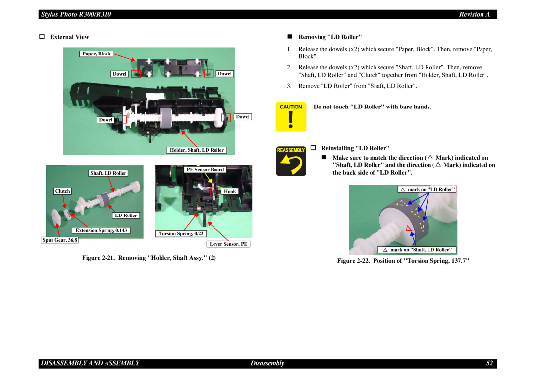
External View
Paper, Block ![]()
Dowel ![]()
![]()
Dowel ![]()
![]()
![]()
![]() Dowel
Dowel
![]()
![]()
![]() Dowel
Dowel
Holder, Shaft, LD Roller
Removing "LD Roller"
1.Release the dowels (x2) which secure "Paper, Block". Then, remove "Paper, Block".
2.Release the dowels (x2) which secure "Shaft, LD Roller". Then, remove "Shaft, LD Roller" and "Clutch" together from "Holder, Shaft, LD Roller".
3.Remove "LD Roller" from "Shaft, LD Roller".
CAUTION Do not touch "LD Roller" with bare hands.
Reinstalling "LD Roller"
Shaft, LD Roller
Clutch
LD Roller
![]()
![]() Extension Spring, 0.143 Spur Gear, 36.8
Extension Spring, 0.143 Spur Gear, 36.8
PE Sensor Board
![]()
![]() Hook
Hook
Torsion Spring, 0.22
Lever Sensor, PE
Make sure to match the direction ( ![]() Mark) indicated on "Shaft, LD Roller" and the direction (
Mark) indicated on "Shaft, LD Roller" and the direction ( ![]() Mark) indicated on the back side of "LD Roller".
Mark) indicated on the back side of "LD Roller".
mark on "LD Roller"
mark on "Shaft, LD Roller"
Figure 2-21. Removing "Holder, Shaft Assy." (2)
Figure 2-22. Position of "Torsion Spring, 137.7"
DISASSEMBLY AND ASSEMBLY | Disassembly | 52 |