Stylus Photo R300/R310 | Revision A |
2.3.16 Removing Power Supply Unit
Procedure for Removing |
External View
Power Supply Unit ![]()
![]() C.B.P 3x10
C.B.P 3x10
C.B.S 3x6
5
4
Hooks
Shield Plate, Upper
2
1
![]()
![]() 3
3
C.B.S 3x6
C.B.S 3x6
1 ![]() 4
4
3 |
| 2 |
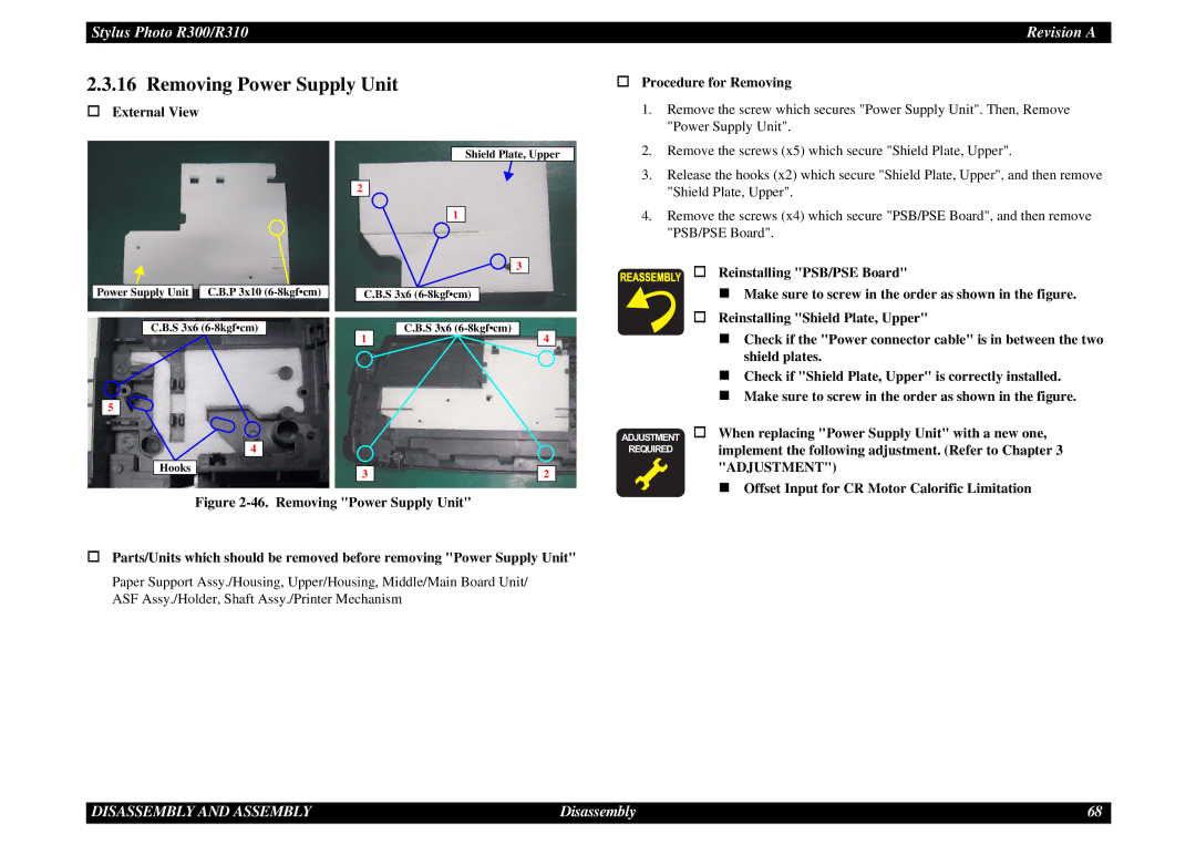
1. | Remove the screw which secures "Power Supply Unit". Then, Remove |
| "Power Supply Unit". |
2. | Remove the screws (x5) which secure "Shield Plate, Upper". |
3. | Release the hooks (x2) which secure "Shield Plate, Upper", and then remove |
| "Shield Plate, Upper". |
4. | Remove the screws (x4) which secure "PSB/PSE Board", and then remove |
| "PSB/PSE Board". |
Reinstalling "PSB/PSE Board"
Make sure to screw in the order as shown in the figure.
Reinstalling "Shield Plate, Upper"
Check if the "Power connector cable" is in between the two shield plates.
Check if "Shield Plate, Upper" is correctly installed.
Make sure to screw in the order as shown in the figure.
ADJUSTMENT When replacing "Power Supply Unit" with a new one,
REQUIRED implement the following adjustment. (Refer to Chapter 3 "ADJUSTMENT")
Offset Input for CR Motor Calorific Limitation
Figure 2-46. Removing "Power Supply Unit"
Parts/Units which should be removed before removing "Power Supply Unit"
Paper Support Assy./Housing, Upper/Housing, Middle/Main Board Unit/ ASF Assy./Holder, Shaft Assy./Printer Mechanism
DISASSEMBLY AND ASSEMBLY | Disassembly | 68 |