Stylus Photo R300/R310 | Revision A |
2.3.9 Removing Holder, Shaft Assy.
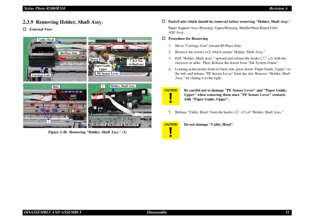
Parts/Units which should be removed before removing "Holder, Shaft Assy." |
External View
Cable, Head
Carriage Unit
2
Dowel ![]()
![]()
Paper Guide, ![]()
![]()
![]()
Upper
PE Sensor Lever
C.B.S 3x6
Paper Support Assy./Housing, Upper/Housing, Middle/Main Board Unit/ | |
ASF Assy. | |
Procedure for Removing | |
1. | Move "Carriage Unit" toward |
2. | Remove the screws (x2) which secure "Holder, Shaft Assy.". |
3. | Pull "Holder, Shaft Assy." upward and release the hooks ( 1 : x2) with the |
| tweezers or alike. Then, Release the dowel from "Ink System Frame". |
4. | Looking at the printer from its back side, press down "Paper Guide, Upper" on |
| the left, and release "PE Sensor Lever" from the slot. Remove "Holder, Shaft |
| Assy." by sliding it to the right. |
Ribs |
| 2 |
| Holder, Shaft Assy. |
|
|
|
|
|
|
|
|
|
|
1
Figure 2-20. Removing "Holder, Shaft Assy." (1)
CAUTION Be careful not to damage "PE Sensor Lever" and "Paper Guide, Upper" when removing them since "PE Sensor Lever" contacts with "Paper Guide, Upper".
5.Release "Cable, Head" from the hooks ( 2 : x7) of "Holder, Shaft Assy.".
CAUTION Do not damage "Cable, Head".
DISASSEMBLY AND ASSEMBLY | Disassembly | 51 |