Stylus Photo R300/R310 | Revision A |
2.3.18 Removing Ink System
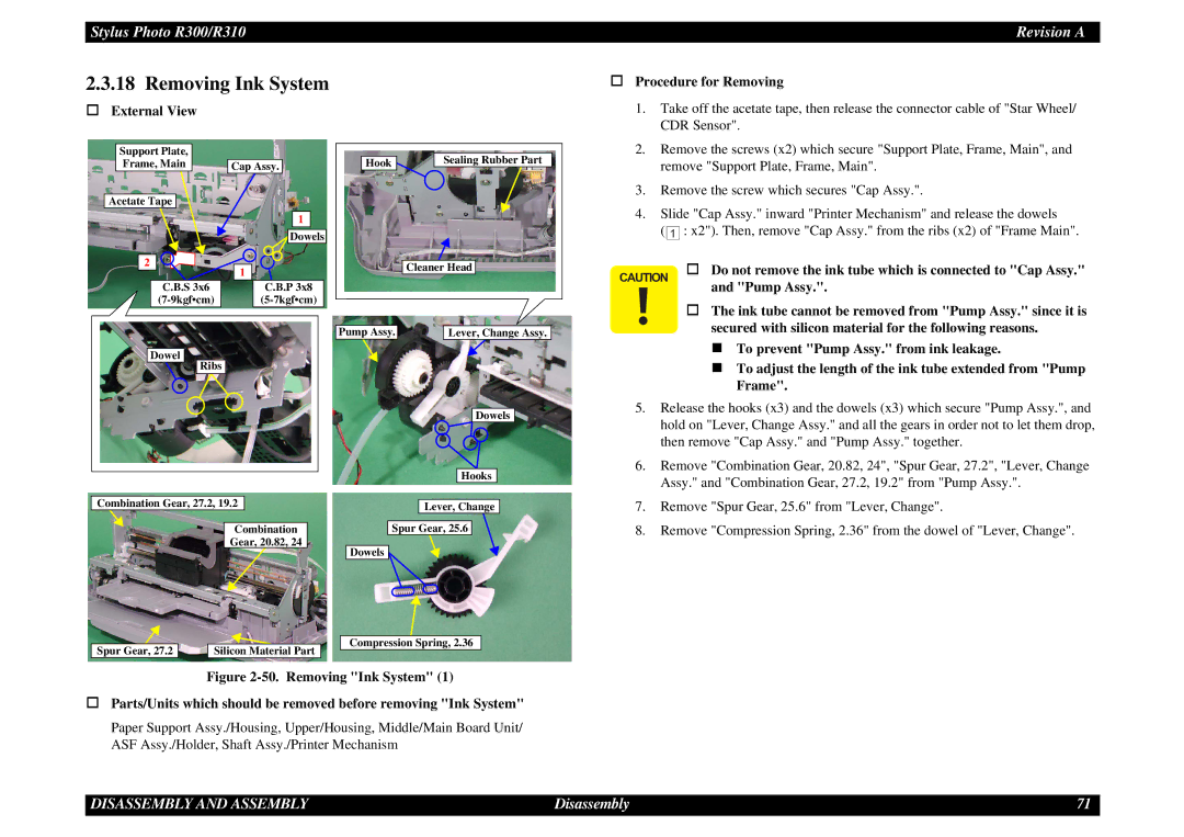
External View
Procedure for Removing |
1. Take off the acetate tape, then release the connector cable of "Star Wheel/ |
CDR Sensor". |
Support Plate, Frame, Main
Acetate Tape
Cap Assy.
1
![]() Dowels
Dowels
Hook | Sealing Rubber Part |
2. | Remove the screws (x2) which secure "Support Plate, Frame, Main", and |
| remove "Support Plate, Frame, Main". |
3. | Remove the screw which secures "Cap Assy.". |
4. | Slide "Cap Assy." inward "Printer Mechanism" and release the dowels |
| ( 1 : x2"). Then, remove "Cap Assy." from the ribs (x2) of "Frame Main". |
2 | 1 |
| |
C.B.S 3x6 | C.B.P 3x8 |
Dowel |
|
Ribs |
|
Cleaner Head |
Pump Assy. |
| Lever, Change Assy. |
Dowels
Hooks
CAUTION | Do not remove the ink tube which is connected to "Cap Assy." |
| and "Pump Assy.". |
The ink tube cannot be removed from "Pump Assy." since it is
secured with silicon material for the following reasons.
| To prevent "Pump Assy." from ink leakage. |
| To adjust the length of the ink tube extended from "Pump |
| Frame". |
5. | Release the hooks (x3) and the dowels (x3) which secure "Pump Assy.", and |
| hold on "Lever, Change Assy." and all the gears in order not to let them drop, |
| then remove "Cap Assy." and "Pump Assy." together. |
6. | Remove "Combination Gear, 20.82, 24", "Spur Gear, 27.2", "Lever, Change |
| Assy." and "Combination Gear, 27.2, 19.2" from "Pump Assy.". |
Combination Gear, 27.2, 19.2 |
|
|
|
| Lever, Change | ||
|
|
|
|
|
|
| |
|
|
|
|
|
|
|
|
|
|
|
|
| Spur Gear, 25.6 |
| |
| Combination | ||||||
| Gear, 20.82, 24 |
|
|
|
|
| |
|
|
|
| Dowels |
|
| |
|
|
| |||||
|
|
|
| Compression Spring, 2.36 |
Spur Gear, 27.2 |
| Silicon Material Part | ||
|
|
|
Figure 2-50. Removing "Ink System" (1)
Parts/Units which should be removed before removing "Ink System"
Paper Support Assy./Housing, Upper/Housing, Middle/Main Board Unit/ ASF Assy./Holder, Shaft Assy./Printer Mechanism
7. | Remove "Spur Gear, 25.6" from "Lever, Change". |
8. | Remove "Compression Spring, 2.36" from the dowel of "Lever, Change". |
DISASSEMBLY AND ASSEMBLY | Disassembly | 71 |