Stylus Photo R300/R310 | Revision A |
CAUTION | When lifting up "Printer Mechanism", "Lever, Change" and |
| "Combination Gear, 27.2, 19.2" may detach and drop. Take care |
| not to drop and damage them. |
When lifting up "Printer Mechanism", take care not to leak and drip ink from the end of "Waste Ink Tube" ("Waste Ink Pads" side).
To prevent "Frame, Main" from warping, do not lift "Printer Mechanism" holding the places which are not specified to hold.
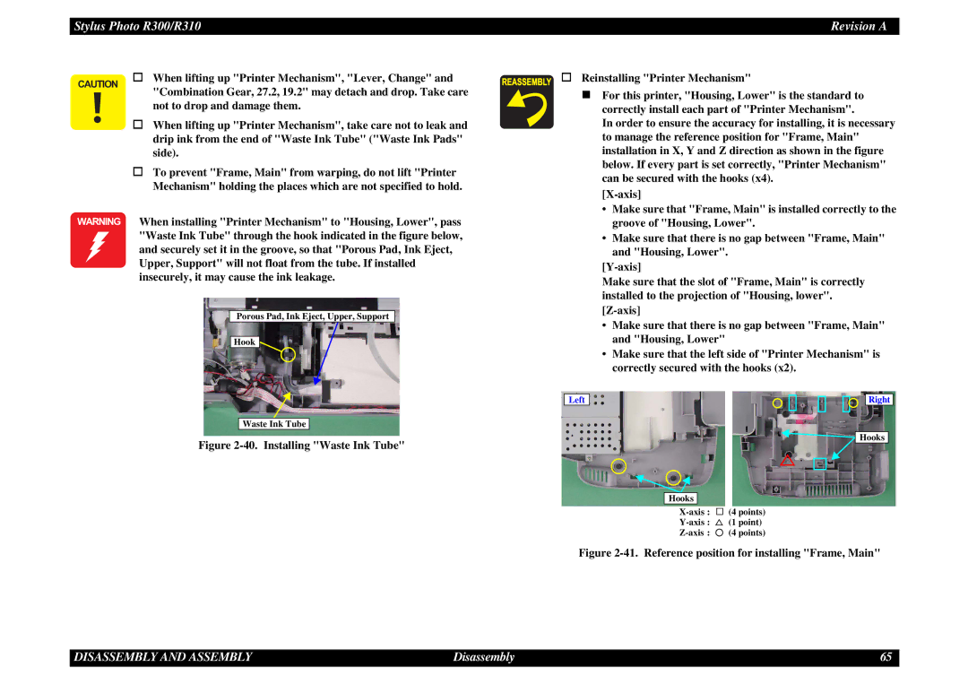
WARNING When installing "Printer Mechanism" to "Housing, Lower", pass "Waste Ink Tube" through the hook indicated in the figure below, and securely set it in the groove, so that "Porous Pad, Ink Eject, Upper, Support" will not float from the tube. If installed insecurely, it may cause the ink leakage.
Porous Pad, Ink Eject, Upper, Support
Hook
Waste Ink Tube
Figure 2-40. Installing "Waste Ink Tube"
Reinstalling "Printer Mechanism"
For this printer, "Housing, Lower" is the standard to correctly install each part of "Printer Mechanism".
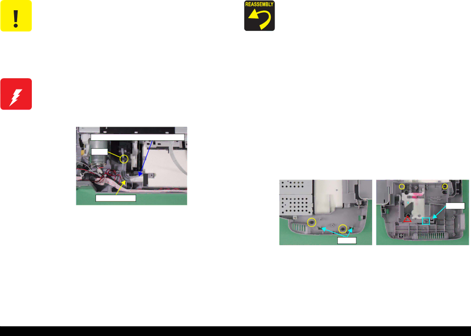
In order to ensure the accuracy for installing, it is necessary to manage the reference position for "Frame, Main" installation in X, Y and Z direction as shown in the figure below. If every part is set correctly, "Printer Mechanism" can be secured with the hooks (x4).
[X-axis]
•Make sure that "Frame, Main" is installed correctly to the groove of "Housing, Lower".
•Make sure that there is no gap between "Frame, Main" and "Housing, Lower".
Make sure that the slot of "Frame, Main" is correctly installed to the projection of "Housing, lower". [Z-axis]
•Make sure that there is no gap between "Frame, Main" and "Housing, Lower"
•Make sure that the left side of "Printer Mechanism" is correctly secured with the hooks (x2).
Left |
|
|
|
|
|
|
| Right |
|
|
|
|
|
|
|
|
|
![]()
![]() Hooks
Hooks
Hooks
![]() (4 points)
(4 points)
![]() (1 point)
(1 point)
![]() (4 points)
(4 points)
Figure 2-41. Reference position for installing "Frame, Main"
DISASSEMBLY AND ASSEMBLY | Disassembly | 65 |