Stylus Photo R300/R310 | Revision A |
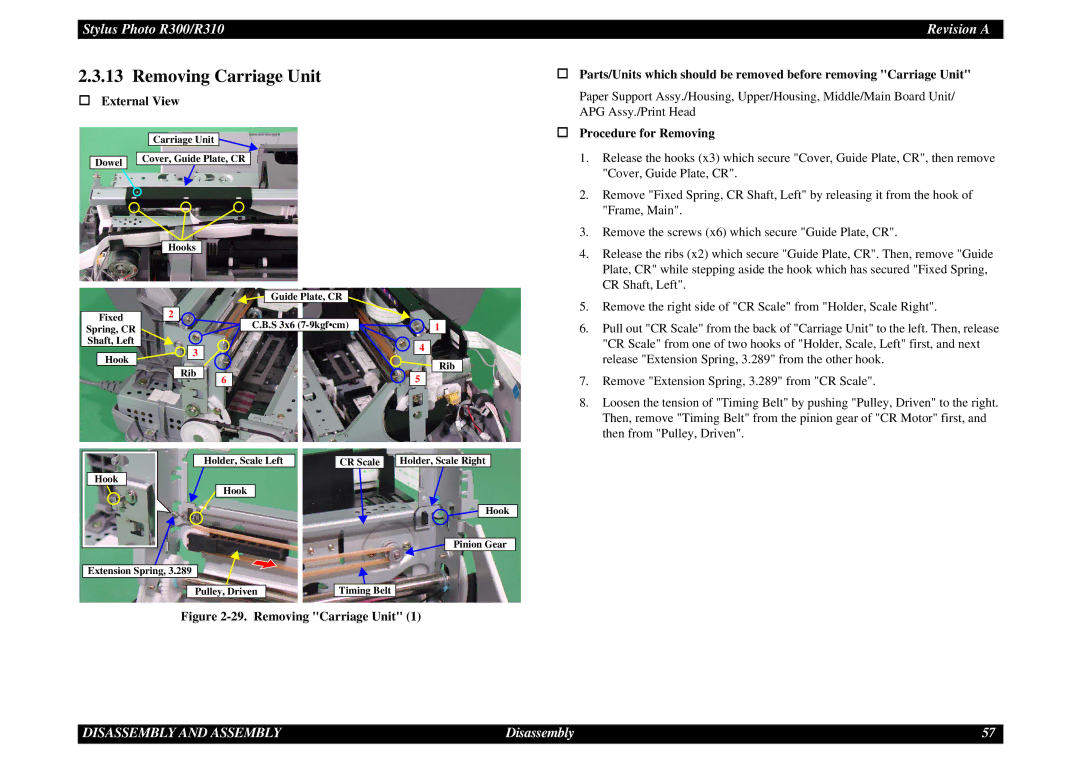
2.3.13 Removing Carriage Unit
External View
Carriage Unit
Dowel ![]()
![]() Cover, Guide Plate, CR
Cover, Guide Plate, CR
|
|
|
| Hooks |
|
|
|
|
|
|
|
|
|
|
|
| |||
|
|
|
|
|
|
|
|
|
|
|
|
|
|
|
|
|
| ||
|
|
|
|
|
|
|
|
|
|
|
| Guide Plate, CR |
|
|
|
|
|
|
|
|
|
|
|
|
|
|
|
|
|
|
|
|
|
|
|
|
|
|
|
|
|
|
| 2 |
|
|
|
|
|
|
|
|
|
|
|
|
|
|
|
| Fixed |
|
|
|
|
|
|
|
|
|
|
|
|
| |||||
Spring, CR |
|
|
|
|
|
|
|
| C.B.S 3x6 |
|
|
| 1 |
| |||||
|
|
|
|
|
|
|
|
|
|
|
|
|
|
|
| ||||
Shaft, Left |
|
|
|
|
|
|
|
|
|
|
|
|
|
|
|
|
| ||
|
|
|
|
|
|
| 3 |
|
|
|
|
|
|
|
| 4 |
|
|
|
| Hook |
|
|
|
|
|
|
|
|
|
|
|
|
|
|
|
| Rib | |
|
|
|
|
|
| Rib |
|
|
|
|
|
|
|
|
|
| |||
|
|
|
|
|
|
| 6 |
|
|
|
|
|
| 5 |
|
|
| ||
|
|
|
|
|
|
|
|
|
|
|
|
|
|
|
|
|
| ||
Parts/Units which should be removed before removing "Carriage Unit"
Paper Support Assy./Housing, Upper/Housing, Middle/Main Board Unit/ APG Assy./Print Head
Procedure for Removing
1.Release the hooks (x3) which secure "Cover, Guide Plate, CR", then remove "Cover, Guide Plate, CR".
2.Remove "Fixed Spring, CR Shaft, Left" by releasing it from the hook of "Frame, Main".
3.Remove the screws (x6) which secure "Guide Plate, CR".
4.Release the ribs (x2) which secure "Guide Plate, CR". Then, remove "Guide Plate, CR" while stepping aside the hook which has secured "Fixed Spring, CR Shaft, Left".
5.Remove the right side of "CR Scale" from "Holder, Scale Right".
6.Pull out "CR Scale" from the back of "Carriage Unit" to the left. Then, release "CR Scale" from one of two hooks of "Holder, Scale, Left" first, and next release "Extension Spring, 3.289" from the other hook.
7.Remove "Extension Spring, 3.289" from "CR Scale".
8.Loosen the tension of "Timing Belt" by pushing "Pulley, Driven" to the right. Then, remove "Timing Belt" from the pinion gear of "CR Motor" first, and then from "Pulley, Driven".
Holder, Scale Left
Hook
Hook
Extension Spring, 3.289
Pulley, Driven
CR Scale |
| Holder, Scale Right |
|
|
|
Hook
Pinion Gear
Timing Belt
Figure 2-29. Removing "Carriage Unit" (1)
DISASSEMBLY AND ASSEMBLY | Disassembly | 57 |