Stylus Photo R300/R310 | Revision A |
2.3.15Removing Printer Mechanism/ Housing, Lower
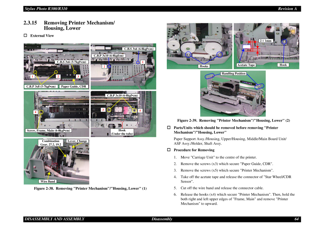
External View
C.B.S 3x6
| 1 |
| 2 |
|
| 3 |
| |
|
|
|
|
|
|
|
|
|
C.B.P 3x8 |
|
|
| Paper Guide, CDR | ||||
C.B.S 3x6
C.B.P 3x10
![]()
![]() 1
1
2
Hooks
2 ± 1mm |
Acetate Tape
Handling Position 
Hook
|
|
| C.B.P 3x10 |
| ||
|
|
|
|
| ||
|
| 3 |
| 5 | ||
4 | ||||||
|
|
|
|
| ||
|
|
|
|
| ||
Screw, Frame, Main |
|
| Hook | |||
|
|
|
|
|
| (Under the tube) |
|
|
|
|
|
| |
Combination | Lever, Change |
|
| |||
| Gear, 27.2, 19.2 |
|
|
|
|
|
Wire Band
Figure 2-38. Removing "Printer Mechanism"/"Housing, Lower" (1)
Figure 2-39. Removing "Printer Mechanism"/"Housing, Lower" (2)
Parts/Units which should be removed before removing "Printer Mechanism"/"Housing, Lower"
Paper Support Assy./Housing, Upper/Housing, Middle/Main Board Unit/ ASF Assy./Holder, Shaft Assy.
Procedure for Removing
1.Move "Carriage Unit" to the centre of the printer.
2.Remove the screws (x3) which secure "Paper Guide, CDR".
3.Remove the screws (x5) which secure "Printer Mechanism".
4.Take off the acetate tape and release the connector of "Star Wheel/CDR Sensor".
5.Cut off the wire band and release the connector cable.
6.Release the hooks (x4) which secure "Printer Mechanism". Then, hold the both right and left upper edges of "Frame, Main" and remove "Printer Mechanism" to upward.
DISASSEMBLY AND ASSEMBLY | Disassembly | 64 |