Stylus Photo R300/R310 | Revision A |
2.3 Disassembly
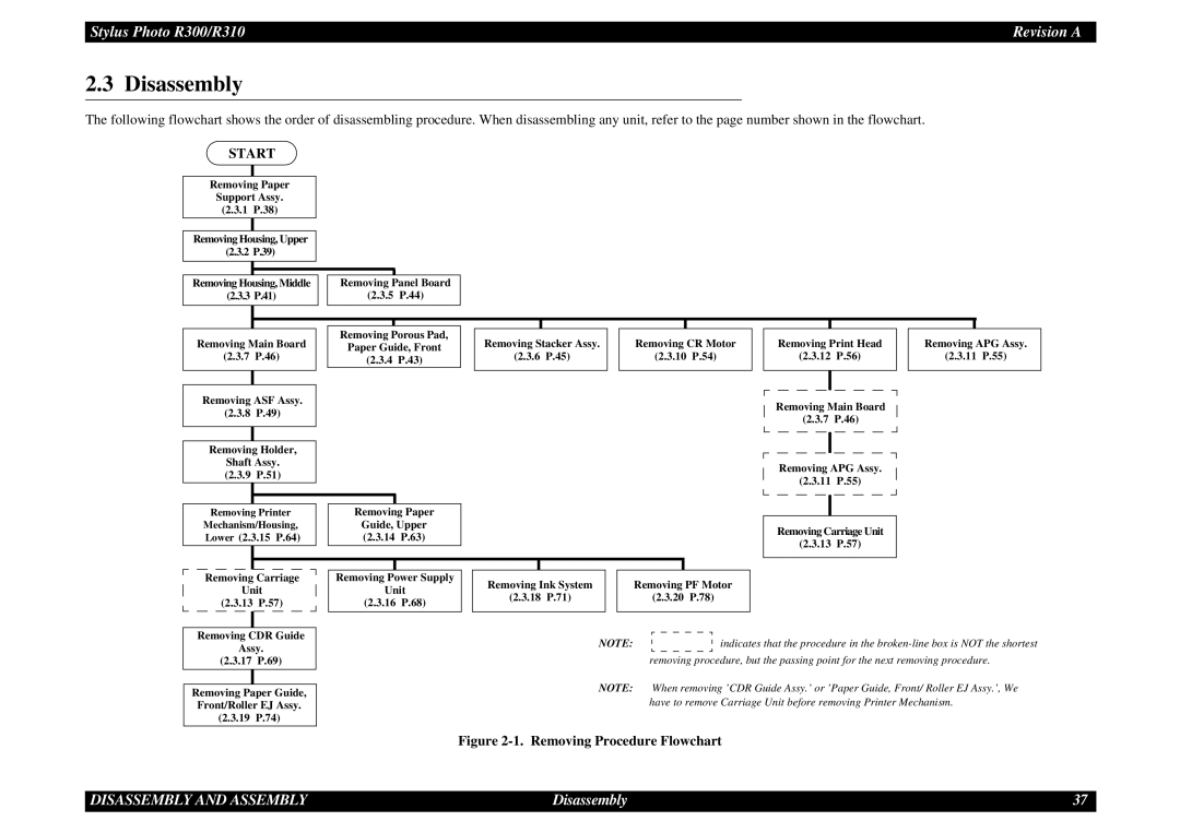
The following flowchart shows the order of disassembling procedure. When disassembling any unit, refer to the page number shown in the flowchart.
START
Removing Paper |
|
|
|
| |
Support Assy. |
|
|
|
| |
(2.3.1 | P.38) |
|
|
|
|
|
|
|
|
|
|
Removing Housing, Upper |
|
|
|
| |
(2.3.2 P.39) |
|
|
|
| |
|
|
|
|
|
|
Removing Housing, Middle |
| Removing |
| Panel Board | |
(2.3.3 P.41) |
| (2.3.5 | P.44) | ||
|
|
|
|
|
|
|
|
|
|
|
|
|
|
|
|
|
|
|
|
|
|
Removing Main Board |
| Removing Porous Pad, | |||||||||||||
| Paper Guide, Front | ||||||||||||||
(2.3.7 | P.46) |
| (2.3.4 | P.43) | |||||||||||
|
|
|
|
|
|
|
|
|
|
|
|
|
|
|
|
|
|
|
|
|
|
|
|
|
|
|
|
|
|
|
|
| Removing ASF Assy. |
|
|
| |||||||||||
(2.3.8 | P.49) |
|
|
| |||||||||||
|
|
|
|
|
|
|
|
|
|
|
|
|
|
| |
|
|
|
|
|
|
|
|
|
|
|
|
|
|
|
|
|
| Removing Holder, |
|
|
| ||||||||||
|
|
| Shaft Assy. |
|
|
| |||||||||
(2.3.9 | P.51) |
|
|
| |||||||||||
|
|
|
|
|
|
|
|
|
|
|
|
|
|
|
|
|
|
|
|
|
|
|
|
|
|
|
|
|
|
|
|
|
| Removing Printer |
| Removing Paper | |||||||||||
| Mechanism/Housing, |
| Guide, Upper | ||||||||||||
| Lower (2.3.15 P.64) |
| (2.3.14 | P.63) | |||||||||||
|
|
|
|
|
|
|
|
|
|
|
|
|
|
|
|
Removing Stacker Assy.
(2.3.6 P.45)
Removing CR Motor
(2.3.10 P.54)
Removing Print Head
(2.3.12 P.56)
Removing Main Board
(2.3.7 P.46)
Removing APG Assy.
(2.3.11 P.55)
Removing Carriage Unit
(2.3.13 P.57)
Removing APG Assy.
(2.3.11 P.55)
Removing Carriage
Unit
(2.3.13 P.57)
Removing CDR Guide
Assy.
(2.3.17 P.69)
Removing Paper Guide,
Front/Roller EJ Assy.
(2.3.19 P.74)
Removing Power Supply
Unit
(2.3.16 P.68)
|
|
|
|
|
|
|
|
|
|
|
|
|
|
|
|
|
Removing Ink System |
|
| Removing PF Motor |
| ||||||||||||
(2.3.18 | P.71) |
|
| (2.3.20 | P.78) |
| ||||||||||
|
|
|
|
|
|
|
|
|
|
|
|
|
|
|
|
|
|
| NOTE: |
|
|
|
|
|
|
|
|
|
| indicates that the procedure in the | |||
|
|
|
|
|
|
|
|
|
|
|
| |||||
|
|
|
|
|
|
|
|
|
|
|
| |||||
|
|
|
|
|
|
|
|
|
|
|
| |||||
|
|
|
|
| removing procedure, but the passing point for the next removing procedure. | |||||||||||
NOTE: When removing ’CDR Guide Assy.’ or ’Paper Guide, Front/ Roller EJ Assy.’, We have to remove Carriage Unit before removing Printer Mechanism.
Figure 2-1. Removing Procedure Flowchart
DISASSEMBLY AND ASSEMBLY | Disassembly | 37 |