Stylus Photo R300/R310 | Revision A |
External View
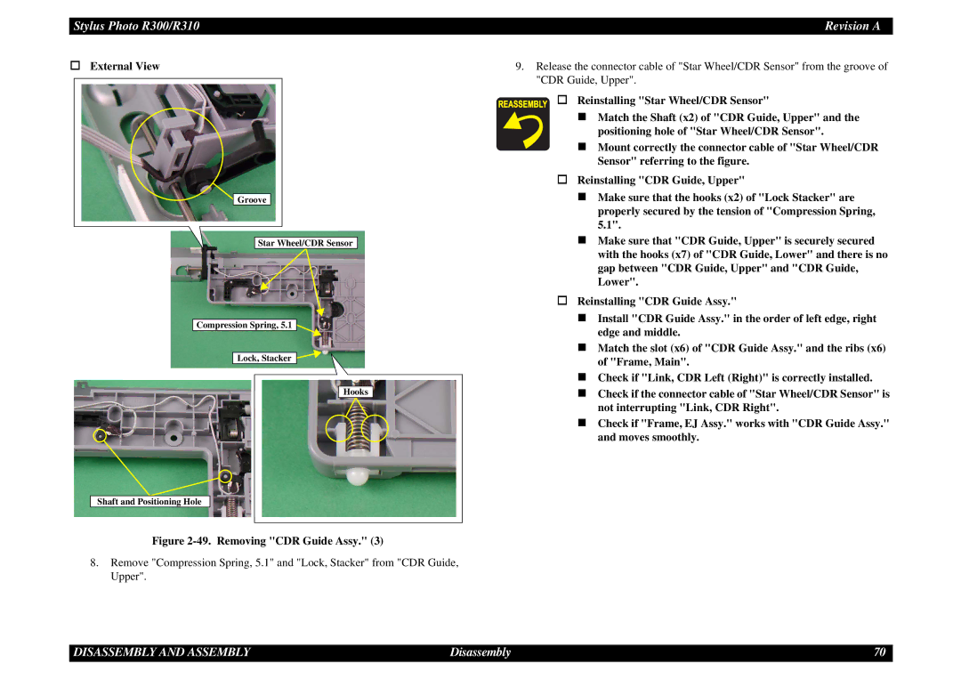
![]() Groove
Groove
Star Wheel/CDR Sensor
Compression Spring, 5.1 ![]()
Lock, Stacker ![]()
![]()
Hooks
Shaft and Positioning Hole
Figure 2-49. Removing "CDR Guide Assy." (3)
8.Remove "Compression Spring, 5.1" and "Lock, Stacker" from "CDR Guide, Upper".
9.Release the connector cable of "Star Wheel/CDR Sensor" from the groove of "CDR Guide, Upper".
Reinstalling "Star Wheel/CDR Sensor"
Match the Shaft (x2) of "CDR Guide, Upper" and the positioning hole of "Star Wheel/CDR Sensor".
Mount correctly the connector cable of "Star Wheel/CDR Sensor" referring to the figure.
Reinstalling "CDR Guide, Upper"
Make sure that the hooks (x2) of "Lock Stacker" are properly secured by the tension of "Compression Spring, 5.1".
Make sure that "CDR Guide, Upper" is securely secured with the hooks (x7) of "CDR Guide, Lower" and there is no gap between "CDR Guide, Upper" and "CDR Guide, Lower".
Reinstalling "CDR Guide Assy."
Install "CDR Guide Assy." in the order of left edge, right edge and middle.
Match the slot (x6) of "CDR Guide Assy." and the ribs (x6) of "Frame, Main".
Check if "Link, CDR Left (Right)" is correctly installed.
Check if the connector cable of "Star Wheel/CDR Sensor" is not interrupting "Link, CDR Right".
Check if "Frame, EJ Assy." works with "CDR Guide Assy." and moves smoothly.
DISASSEMBLY AND ASSEMBLY | Disassembly | 70 |
