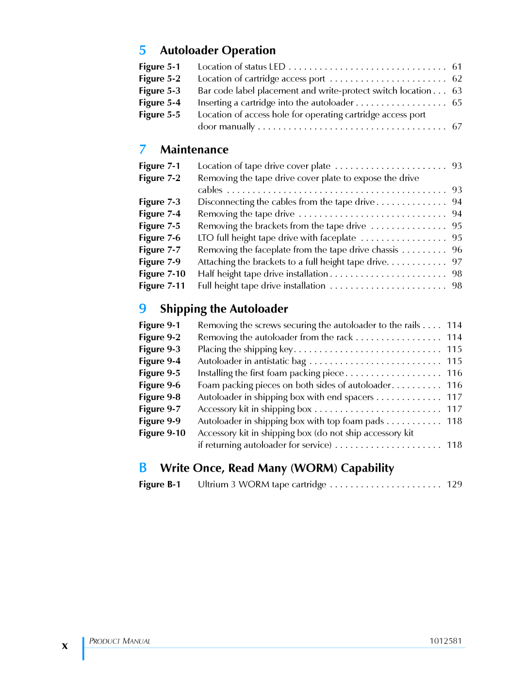
5Autoloader Operation
Figure 5-1 Location of status LED . . . . . . . . . . . . . . . . . . . . . . . . . . . . . . . 61 Figure 5-2 Location of cartridge access port . . . . . . . . . . . . . . . . . . . . . . . 62 Figure 5-3 Bar code label placement and write-protect switch location . . . 63 Figure 5-4 Inserting a cartridge into the autoloader . . . . . . . . . . . . . . . . . . 65 Figure 5-5 Location of access hole for operating cartridge access port
door manually . . . . . . . . . . . . . . . . . . . . . . . . . . . . . . . . . . . . . 67
7Maintenance
Figure 7-1 Location of tape drive cover plate . . . . . . . . . . . . . . . . . . . . . . 93 Figure 7-2 Removing the tape drive cover plate to expose the drive
cables . . . . . . . . . . . . . . . . . . . . . . . . . . . . . . . . . . . . . . . . . . . 93 Figure 7-3 Disconnecting the cables from the tape drive . . . . . . . . . . . . . . 94 Figure 7-4 Removing the tape drive . . . . . . . . . . . . . . . . . . . . . . . . . . . . . 94 Figure 7-5 Removing the brackets from the tape drive . . . . . . . . . . . . . . . 95 Figure 7-6 LTO full height tape drive with faceplate . . . . . . . . . . . . . . . . . 95 Figure 7-7 Removing the faceplate from the tape drive chassis . . . . . . . . . 96 Figure 7-9 Attaching the brackets to a full height tape drive. . . . . . . . . . . . 97 Figure 7-10 Half height tape drive installation . . . . . . . . . . . . . . . . . . . . . . . 98 Figure 7-11 Full height tape drive installation . . . . . . . . . . . . . . . . . . . . . . . 98
9Shipping the Autoloader
Figure 9-1 Removing the screws securing the autoloader to the rails . . . . 114 Figure 9-2 Removing the autoloader from the rack . . . . . . . . . . . . . . . . . 114 Figure 9-3 Placing the shipping key. . . . . . . . . . . . . . . . . . . . . . . . . . . . . 115 Figure 9-4 Autoloader in antistatic bag . . . . . . . . . . . . . . . . . . . . . . . . . . 115 Figure 9-5 Installing the first foam packing piece . . . . . . . . . . . . . . . . . . . 116 Figure 9-6 Foam packing pieces on both sides of autoloader . . . . . . . . . . 116 Figure 9-8 Autoloader in shipping box with end spacers . . . . . . . . . . . . . 117 Figure 9-7 Accessory kit in shipping box . . . . . . . . . . . . . . . . . . . . . . . . . 117 Figure 9-9 Autoloader in shipping box with top foam pads . . . . . . . . . . . 118 Figure 9-10 Accessory kit in shipping box (do not ship accessory kit
if returning autoloader for service) . . . . . . . . . . . . . . . . . . . . . 118
BWrite Once, Read Many (WORM) Capability
Figure B-1 Ultrium 3 WORM tape cartridge . . . . . . . . . . . . . . . . . . . . . . 129
x
| PRODUCT MANUAL | 1012581 |
| ||
|
|
|
|
|
|
