6 |
5. Insert the third output field and its key functions into the picture:
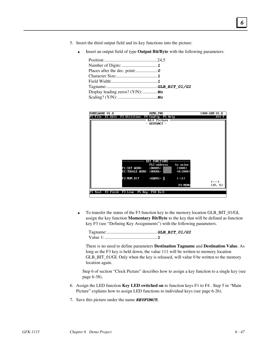
●Insert an output field of type Output Bit/Byte with the following parameters:
Position: | 24,5 |
Number of Digits: | 1 |
Places after the dec. point: | 0 |
Character Size: | 1 |
Field Width: | 1 |
Tagname: | GLB_BIT_01/GI |
Display leading zeros? (Y/N): | No |
Scaling? (Y/N): | No |
●To transfer the status of the F3 function key to the memory location GLB_BIT_01/GI, assign the key function Momentary Bit/Byte to the key that will be defined as function key F3 (see “Defining Key Assignments”) with the following parameters.
Tagname: | GLB_BIT_01/GI |
Value 1: | 1 |
There is no need to define parameters Destination Tagname and Destination Value. As long as the F3 key is held down, the value 111 will be written to memory location GLB_BIT_01/GI. Only when the key is released, will value 0 be written to the memory location again.
Step 6 of section “Clock Picture” describes how to assign a key function to a single key (see page
6.Assign the LED function Key LED switched on to function keys F1 to F4 . Step 5 in “Main Picture” explains how to assign LED functions to individual keys (see page
7.Save this picture under the name KEYFUNCT.
| Chapter 6 Demo Project | 6 - 47 |