Using 2-Wire Latching Glassbreaks on Zone 8
Zone 8 can support
Compatible Glassbreak Detectors
Use detectors that meet the following ratings:
GLASSBREAK
DETECTOR
2000 | ZONE 8 | (+) |
21 | ||
OHMS |
|
|
EOLR | LATCHING TYPE GLASS |
|
|
| |
| BREAK DETECTOR LOOP | |
| 22 | |
|
|
Standby
Voltage:
Standby Resistance:
Alarm Resistance:
Alarm
Current:
Reset Time:
Greater than 20k ohms (equivalent resistance of all detectors in parallel)
Less than 1.1k ohms (see note below)
Less than 6 seconds
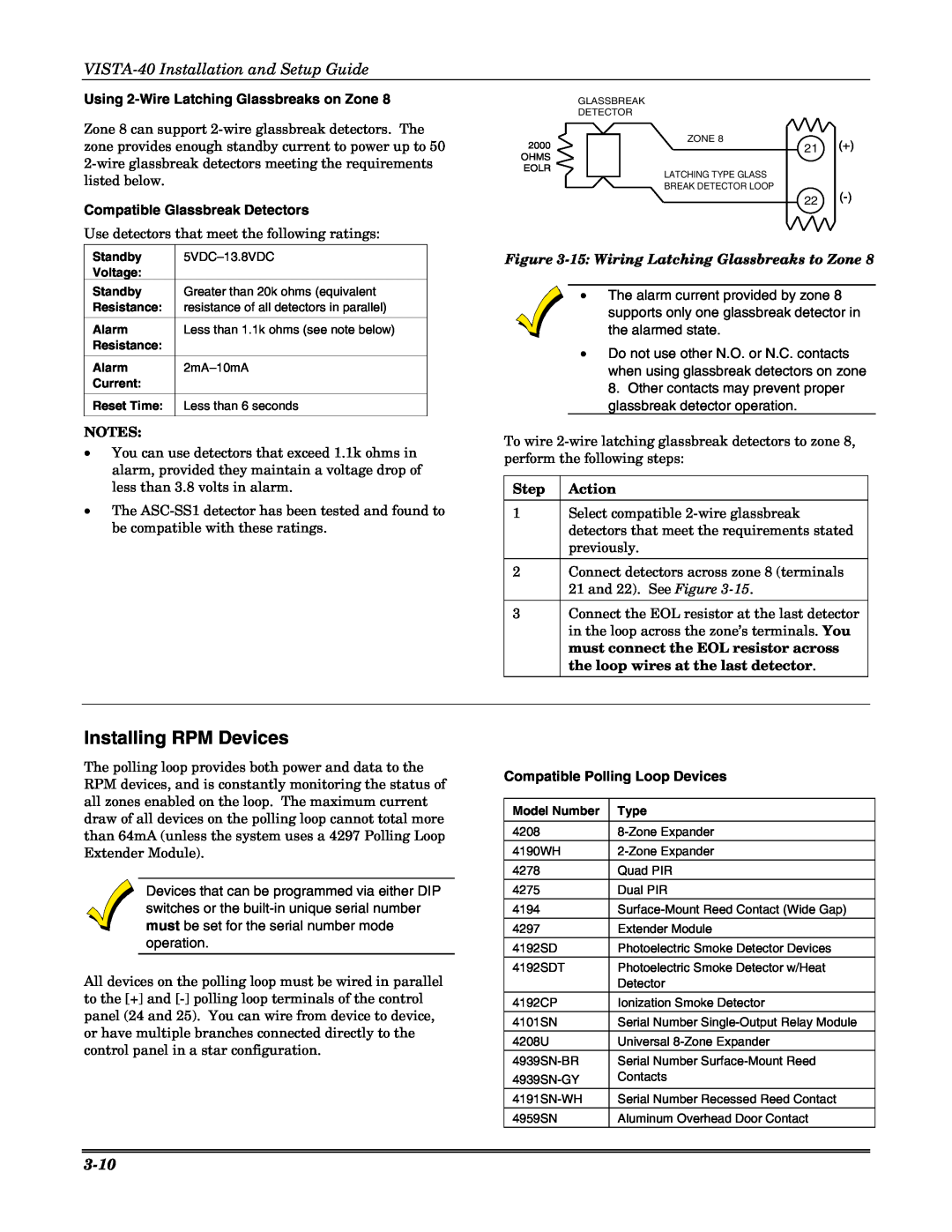
Figure
•The alarm current provided by zone 8 supports only one glassbreak detector in the alarmed state.
•Do not use other N.O. or N.C. contacts when using glassbreak detectors on zone 8. Other contacts may prevent proper glassbreak detector operation.
NOTES:
•You can use detectors that exceed 1.1k ohms in alarm, provided they maintain a voltage drop of less than 3.8 volts in alarm.
•The
To wire
Step Action
1Select compatible
2Connect detectors across zone 8 (terminals 21 and 22). See Figure
3Connect the EOL resistor at the last detector in the loop across the zone’s terminals. You must connect the EOL resistor across the loop wires at the last detector.
Installing RPM Devices
The polling loop provides both power and data to the RPM devices, and is constantly monitoring the status of all zones enabled on the loop. The maximum current
Compatible Polling Loop Devices
draw of all devices on the polling loop cannot total more than 64mA (unless the system uses a 4297 Polling Loop Extender Module).
Devices that can be programmed via either DIP switches or the
All devices on the polling loop must be wired in parallel to the [+] and
Model Number
4208
4190WH
4278
4275
4194
4297
4192SD
4192SDT
4192CP
4101SN
4208U
4959SN
Type
Quad PIR
Dual PIR
Extender Module
Photoelectric Smoke Detector Devices
Photoelectric Smoke Detector w/Heat Detector
Ionization Smoke Detector
Serial Number
Universal
Serial Number
Serial Number Recessed Reed Contact
Aluminum Overhead Door Contact