FIELD | TITLE and DATA ENTRIES | EXPLANATION |
|
|
|
| 1*36 |
| ID Digit for Zones |
|
|
| |
|
|
|
|
|
|
| Alarm Code for Zones |
| 1*37 |
| |
|
|
| |
|
|
|
|
|
|
| ID Digit for Zones |
| 1*38 |
| |
|
|
| |
|
|
|
|
|
|
| Supervisory and Restore Codes |
| 1*39 |
| |
|
| for Zones | |
|
|
| |
|
|
| Enter |
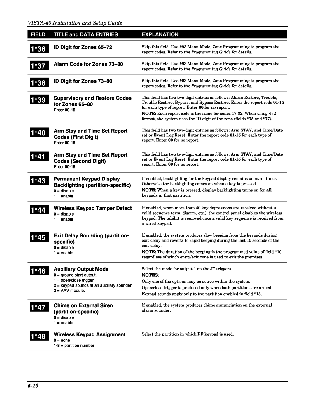
Skip this field. Use #93 Menu Mode, Zone Programming to program the report codes. Refer to the Programming Guide for details.
Skip this field. Use #93 Menu Mode, Zone Programming to program the report codes. Refer to the Programming Guide for details.
Skip this field. Use #93 Menu Mode, Zone Programming to program the report codes. Refer to the Programming Guide for details.
This field has five
NOTE: Each report code is the same for zones
| 1*40 |
| Arm Stay and Time Set Report | |
|
| Codes (First Digit) | ||
|
|
| ||
|
|
| Enter | |
|
|
|
| |
|
|
| Arm Stay and Time Set Report | |
| 1*41 |
| ||
|
| Codes (Second Digit) | ||
|
|
| ||
|
|
| Enter | |
|
|
|
| |
|
|
| Permanent Keypad Display | |
| 1*43 |
| ||
|
| Backlighting | ||
|
|
| ||
|
| 0 | = disable | |
|
| 1 | = enable | |
|
|
|
| |
|
|
| Wireless Keypad Tamper Detect | |
| 1*44 |
| ||
| 0 | = disable | ||
|
| |||
|
| 1 | = enable | |
|
|
|
| |
|
|
| Exit Delay Sounding (partition- | |
| 1*45 |
| ||
|
| specific) | ||
|
|
| ||
|
| 0 | = disable | |
|
| 1 | = enable | |
|
|
|
| |
|
|
| Auxiliary Output Mode | |
| 1*46 |
| ||
| 0 | = ground start output. | ||
|
| |||
|
| 1 | = open/close trigger. | |
|
| 2 | = keypad sounds at an auxiliary sounder. | |
|
| 3 | = AAV module. | |
|
|
|
| |
|
|
| Chime on External Siren | |
| 1*47 |
| ||
|
| |||
|
|
| ||
|
| 0 | = disable | |
|
| 1 | = enable | |
|
|
|
| |
|
|
| Wireless Keypad Assignment | |
| 1*48 |
| ||
| 0 | = none | ||
|
| |||
This field has two
This field has two
If enabled, backlighting for the keypad display remains on at all times. Otherwise the backlighting comes on when a key is pressed.
NOTE: When a key is pressed, display backlighting turns on for all keypads in that partition.
If enabled, when more than 40 key depressions are received without a valid sequence (arm, disarm, etc.), the control panel disables the wireless keypad. The inhibit is removed once a valid key sequence is received from a wired keypad.
If enabled, the system produces slow beeping from the keypads during exit delay and reverts to rapid beeping during the last 10 seconds of the exit delay.
NOTE: The duration of the beeping is the programmed value of field *10 regardless of which entry/exit zone is used to exit the premises.
Select the mode for output 1 on the J7 triggers.
NOTES:
Only one of the options may be active within the system.
Open/close trigger is produced only when both partitions are armed.
Keypad sounds apply only to the partition enabled in field *15.
If enabled, the system produces chime annunciation on the external alarm sounder.
Select the partition in which RF keypad is used.
