Section 5 – Data Field Descriptions
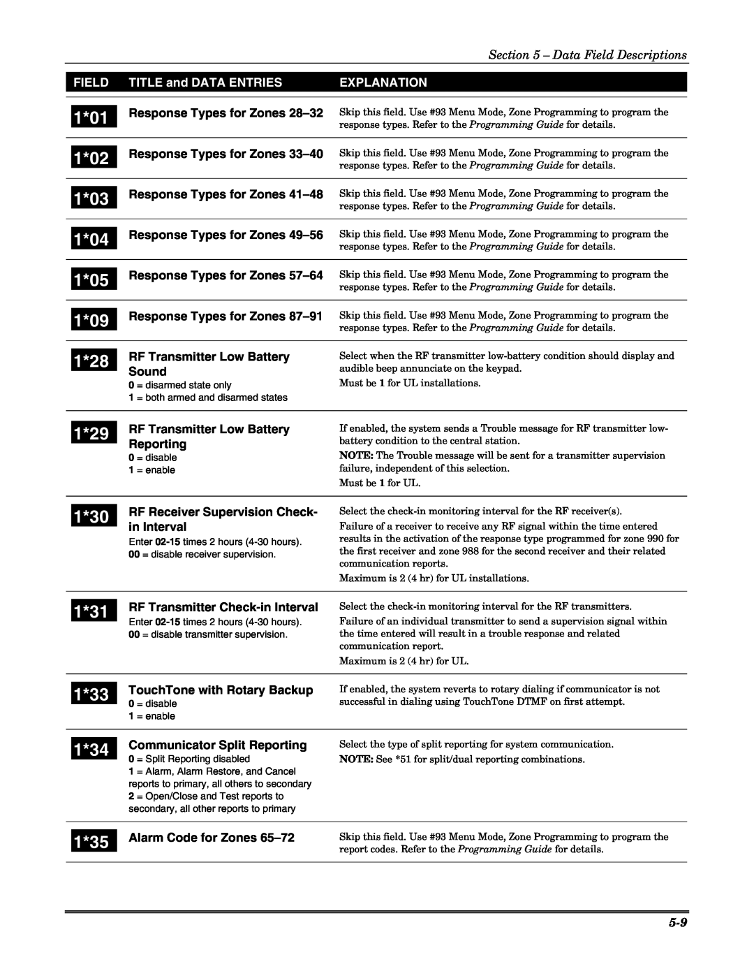
FIELD | TITLE and DATA ENTRIES | EXPLANATION |
|
|
|
1*01
1*02
1*03
1*04
1*05
1*09
1*28
1*29
1*30
Response Types for Zones 28–32
Response Types for Zones 33–40
Response Types for Zones 41–48
Response Types for Zones 49–56
Response Types for Zones 57–64
Response Types for Zones 87–91
RF Transmitter Low Battery Sound
0 = disarmed state only
1 = both armed and disarmed states
RF Transmitter Low Battery Reporting
0 = disable
1 = enable
RF Receiver Supervision Check- in Interval
Enter
Skip this field. Use #93 Menu Mode, Zone Programming to program the response types. Refer to the Programming Guide for details.
Skip this field. Use #93 Menu Mode, Zone Programming to program the response types. Refer to the Programming Guide for details.
Skip this field. Use #93 Menu Mode, Zone Programming to program the response types. Refer to the Programming Guide for details.
Skip this field. Use #93 Menu Mode, Zone Programming to program the response types. Refer to the Programming Guide for details.
Skip this field. Use #93 Menu Mode, Zone Programming to program the response types. Refer to the Programming Guide for details.
Skip this field. Use #93 Menu Mode, Zone Programming to program the response types. Refer to the Programming Guide for details.
Select when the RF transmitter
Must be 1 for UL installations.
If enabled, the system sends a Trouble message for RF transmitter low- battery condition to the central station.
NOTE: The Trouble message will be sent for a transmitter supervision failure, independent of this selection.
Must be 1 for UL.
Select the
Failure of a receiver to receive any RF signal within the time entered results in the activation of the response type programmed for zone 990 for the first receiver and zone 988 for the second receiver and their related communication reports.
Maximum is 2 (4 hr) for UL installations.
1*31 | RF Transmitter | |
Enter | ||
| ||
| 00 = disable transmitter supervision. |
Select the
Failure of an individual transmitter to send a supervision signal within the time entered will result in a trouble response and related communication report.
Maximum is 2 (4 hr) for UL.
| 1*33 |
| TouchTone with Rotary Backup | |
| 0 | = disable | ||
|
| |||
|
| 1 | = enable | |
|
|
|
| |
|
|
| Communicator Split Reporting | |
| 1*34 |
| ||
| 0 | = Split Reporting disabled | ||
|
| |||
|
| 1 | = Alarm, Alarm Restore, and Cancel | |
|
|
| reports to primary, all others to secondary | |
|
| 2 | = Open/Close and Test reports to | |
|
|
| secondary, all other reports to primary | |
|
|
|
|
|
If enabled, the system reverts to rotary dialing if communicator is not successful in dialing using TouchTone DTMF on first attempt.
Select the type of split reporting for system communication.
NOTE: See *51 for split/dual reporting combinations.
| 1*35 |
| Alarm Code for Zones | Skip this field. Use #93 Menu Mode, Zone Programming to program the |
|
|
| report codes. Refer to the Programming Guide for details. | |
|
|
|
| |
|
|
|
|
|