Power Limiting Outputs
All outputs are
Output | Maximum Current Draw |
Auxiliary Power | 750mA |
Polling Loop | 64mA |
Alarm Output | 1.7A |
For Household Fire or Combination Household
Fire/Burglary Installation: The total current drawn from the auxiliary power, the polling loop, and the alarm output combined must not exceed 750mA to comply with the battery independence requirements in UL985.
For Household
Failure to observe the polling loop current rating will cause polling loop malfunction. Failure to observe the auxiliary power current rating will result in a battery that does not charge properly or possibly a tripped circuit breaker.
To connect the transformer to the control, perform the following steps:
Step Action
1Connect all installed devices to the control.
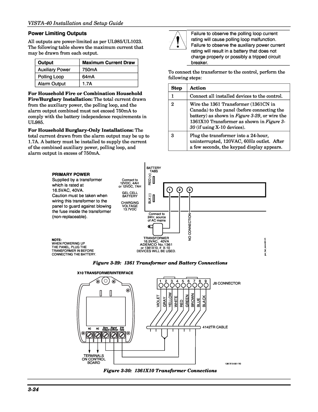
2Wire the 1361 Transformer (1361CN in Canada) to the panel (before connecting the battery) as shown in Figure
3Plug the transformer into a
PRIMARY POWER
Supplied by a transformer which is rated at 16.5VAC, 40VA.
Caution must be taken when wiring this transformer to the panel to guard against blowing the fuse inside the transformer
NOTE:
WHEN POWERING UP
THE PANEL, PLUG THE
TRANSFORMER IN BEFORE
CONNECTING THE BATTERY.
| BATTERY |
|
|
|
| TABS |
|
|
|
| (+) |
|
|
|
Connect to | RED |
|
|
|
12VDC, 4AH |
|
|
| |
or 12VDC, 7AH |
|
|
| |
GEL CELL | 1 | 2 | 3 |
|
) |
|
|
| |
BATTERY | (- |
|
|
|
BLK |
|
|
| |
CHARGING |
|
|
| |
VOLTAGE |
|
|
|
|
13.7VDC |
|
|
|
|
| Connect to |
| CONNECTION |
|
| 24hr. source |
|
| |
| of AC mains |
|
|
|
| TRANSFORMER |
| NO | |
| 16.5VAC, 40VA |
| ||
| ADEMCO No.1361 |
|
| - |
| or 1361X10, if |
|
| conn |
|
|
| bat_ | |
DEVICES WILL BE USED. |
|
| ||
|
|
|
| pwr |
Figure
X10 TRANSFORMER/INTERFACE
AC | AC | Sync Signal | X10 |
OutputCommon | Data |
TERMINALS
ON CONTROL
BOARD
1 | 2 | 3 | 4 | 5 | 6 | 7 | 8 | 9 |
|
|
|
|
|
|
|
| J8 CONNECTOR |
VIOLET | GRAY | YELLOW | WHITE | RED | GREEN | BROWN | BLUE | BLA CK |
|
|
|
|
|
|
|
| 4142TR CABLE |
Figure