A P P E N D I X C
Specifications
• • • • • • • • • • • • • • • • • • • • • • • • • • • • • • • • • • • • • • • • • • • • • • • • • •
VISTA-40 CONTROL
Physical: |
|
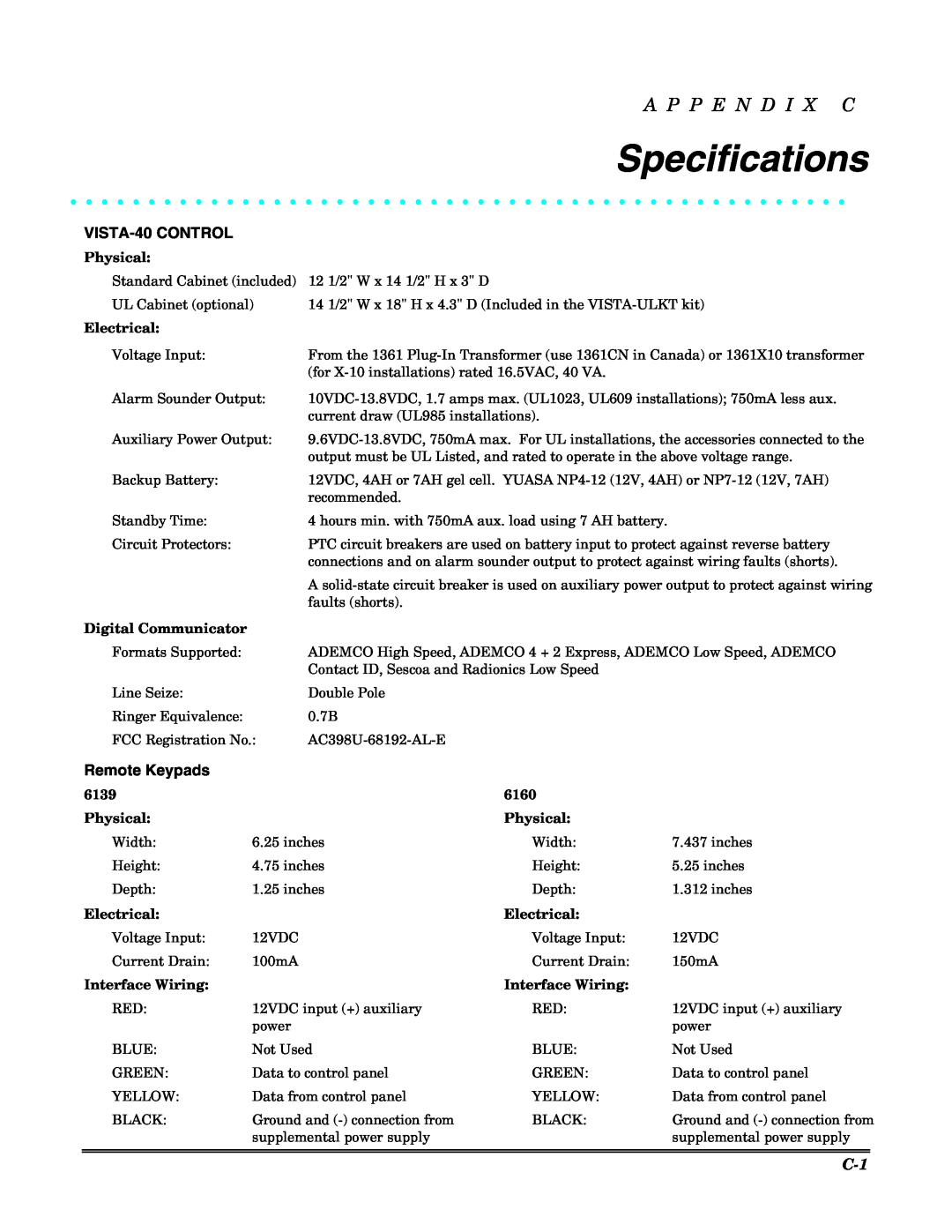
Standard Cabinet (included) | 12 1/2" W x 14 1/2" H x 3" D |
UL Cabinet (optional) | 14 1/2" W x 18" H x 4.3" D (Included in the |
Electrical: |
|
Voltage Input: | From the 1361 |
| (for |
Alarm Sounder Output: | |
| current draw (UL985 installations). |
Auxiliary Power Output: | |
| output must be UL Listed, and rated to operate in the above voltage range. |
Backup Battery: | 12VDC, 4AH or 7AH gel cell. YUASA |
| recommended. |
Standby Time: | 4 hours min. with 750mA aux. load using 7 AH battery. |
Circuit Protectors: | PTC circuit breakers are used on battery input to protect against reverse battery |
| connections and on alarm sounder output to protect against wiring faults (shorts). |
| A |
| faults (shorts). |
Digital Communicator |
|
Formats Supported: | ADEMCO High Speed, ADEMCO 4 + 2 Express, ADEMCO Low Speed, ADEMCO |
| Contact ID, Sescoa and Radionics Low Speed |
Line Seize: | Double Pole |
Ringer Equivalence: | 0.7B |
FCC Registration No.: |
Remote Keypads
6139 |
| 6160 |
|
Physical: |
| Physical: |
|
Width: | 6.25 inches | Width: | 7.437 inches |
Height: | 4.75 inches | Height: | 5.25 inches |
Depth: | 1.25 inches | Depth: | 1.312 inches |
Electrical: |
| Electrical: |
|
|
Voltage Input: | 12VDC | Voltage Input: | 12VDC | |
Current Drain: | 100mA | Current Drain: | 150mA | |
Interface Wiring: |
| Interface Wiring: |
|
|
RED: | 12VDC input (+) auxiliary | RED: | 12VDC input (+) auxiliary | |
| power |
| power | |
BLUE: | Not Used | BLUE: | Not Used | |
GREEN: | Data to control panel | GREEN: | Data to control panel | |
YELLOW: | Data from control panel | YELLOW: | Data from control panel | |
BLACK: | Ground and | BLACK: | Ground and | |
| supplemental power supply |
| supplemental power supply | |
|
|
|
|
|
|
|
|
|
|
|
|
| ||
