To install the 5881 RF receiver, perform the following steps:
Step Action
1Mount the receiver, following the advisories stated previously.
2Set the DIP switches in the receiver for the address
Make sure the address setting is not being used by another device (keypad, relay module, etc.).
3If installing a 5881ENHC, install a
Step
4
5
Action
Connect the receiver’s wire harness to the keypad terminals (6, 7, 8, and 9). Plug the connector at the other end of the harness into the receiver.
Refer to the Installation Instructions provided with the receiver for installations regarding antenna mounting, etc.
CIRCUIT
BOARD
MOUNTING
HOLES
ANTENNAS
INSERT IN
YELLOW |
RED |
BLACK |
GREEN |
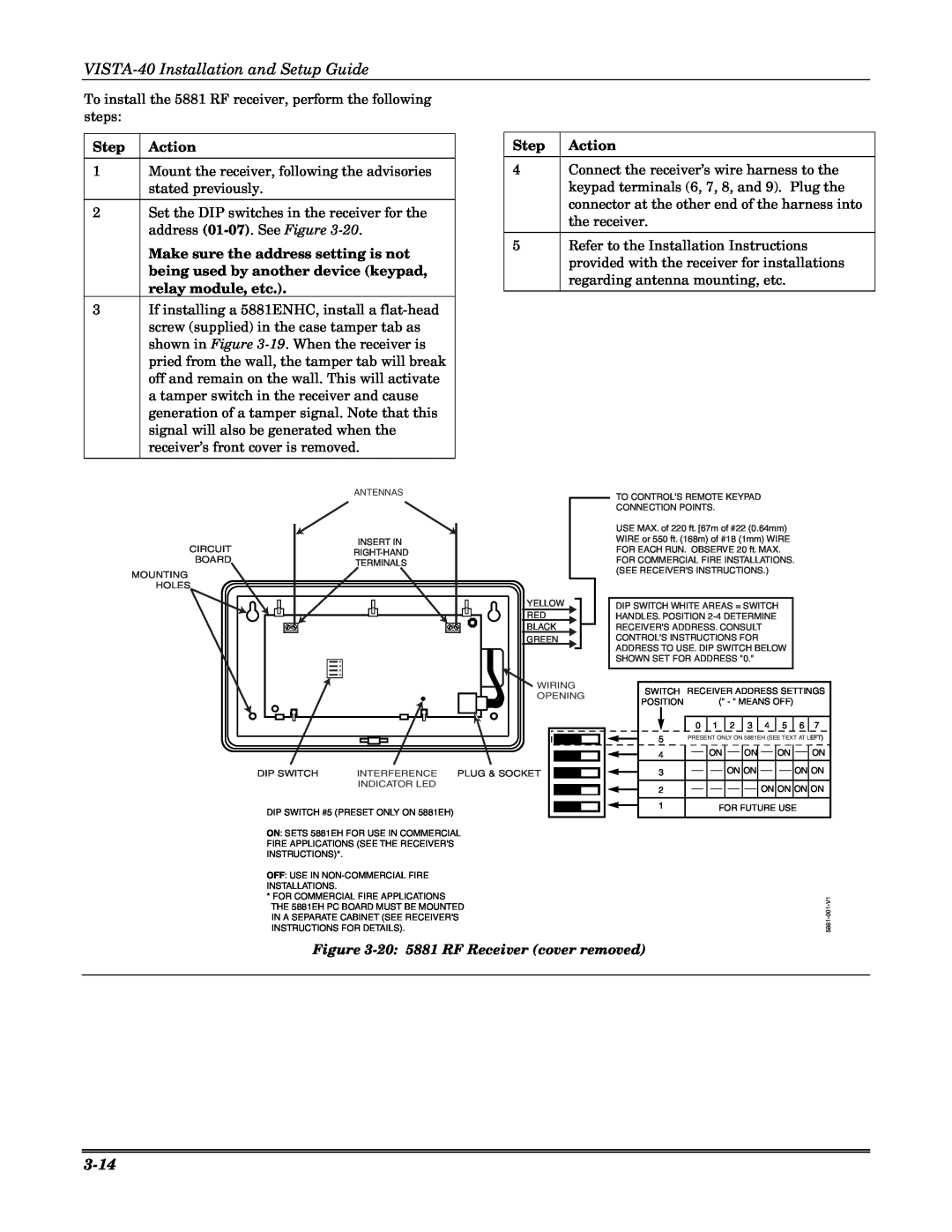
TO CONTROL'S REMOTE KEYPAD CONNECTION POINTS.
USE MAX. of 220 ft. [67m of #22 (0.64mm) WIRE or 550 ft. (168m) of #18 (1mm) WIRE FOR EACH RUN. OBSERVE 20 ft. MAX.
FOR COMMERCIAL FIRE INSTALLATIONS. (SEE RECEIVER'S INSTRUCTIONS.)
DIP SWITCH WHITE AREAS = SWITCH HANDLES. POSITION
|
| WIRING | SWITCH | RECEIVER ADDRESS SETTINGS | |||||||
|
| OPENING | |||||||||
|
| POSITION |
| (" - " MEANS OFF) |
|
| |||||
|
|
|
|
|
| ||||||
|
|
|
| 0 | 1 | 2 | 3 | 4 | 5 | 6 | 7 |
|
|
| 5 | PRESENT ONLY ON 5881EH (SEE TEXT AT LEFT) | |||||||
|
|
| 4 |
| ON |
| ON |
| ON |
| ON |
DIP SWITCH | INTERFERENCE | PLUG & SOCKET | 3 |
|
| ON ON |
|
| ON ON | ||
| INDICATOR LED |
| 2 |
|
|
|
| ON ON ON ON | |||
|
|
|
|
|
|
| |||||
DIP SWITCH #5 (PRESET ONLY ON 5881EH) |
| 1 |
| FOR FUTURE USE |
| ||||||
|
|
|
|
|
|
|
|
|
| ||
ON: SETS 5881EH FOR USE IN COMMERCIAL
FIRE APPLICATIONS (SEE THE RECEIVER'S
INSTRUCTIONS)*.
OFF: USE IN |
| |
INSTALLATIONS. |
| |
* FOR COMMERCIAL FIRE APPLICATIONS | ||
THE 5881EH PC BOARD MUST BE MOUNTED | ||
IN A SEPARATE CABINET (SEE RECEIVER'S | ||
5881 | ||
INSTRUCTIONS FOR DETAILS). |
Figure