Model Number Type
7500 |
| Single Technology Glassbreak Detector |
|
9500 |
| Dual Technology Glassbreak Detector |
|
4209U |
| Universal Group Zoning Module |
|
4193SN |
| Serialized |
|
4293SN |
| Serialized |
|
4190SN |
| Serialized |
|
998MX |
| Serialized PIR |
|
|
|
| |
UL | • The 4208 must be mounted either inside the |
| |
control panel’s cabinet or in a separate |
| ||
enclosure that has a
• The 4190WH right loop must not be used, and the left loop must be
• The 4278 right loop cannot be used.
• The 4194 is not UL Listed.
• The 4297 must be powered from the control panel’s Auxiliary Power Output or from a UL Listed supplementary power supply.
• The 7500 and 9500 detectors are not UL Listed.
• For new polling loop installations, always use twisted pair wiring. In many cases, existing
• Always locate polling loop wiring at least six inches (15cm) of AC power, telephone, or intercom wiring. The polling loop carries data between the control panel and the devices; interference on this loop can cause an interruption of communication. The polling loop can also cause outgoing interference on the intercom or phone lines. If this spacing cannot be achieved, shielded wire must be used. (Note that the maximum total wire length supported is cut in half when shielded wire is used.)
Section 3 - Installing the Control
To install polling loop devices, perform the following steps:
Step Action
1Select devices from the list of compatible devices shown previously.
2Set the DIP switches in the device (if required). Refer to the device’s instructions for the DIP Switch Tables.
3Mount each device in the desired location. Refer to the device’s instructions.
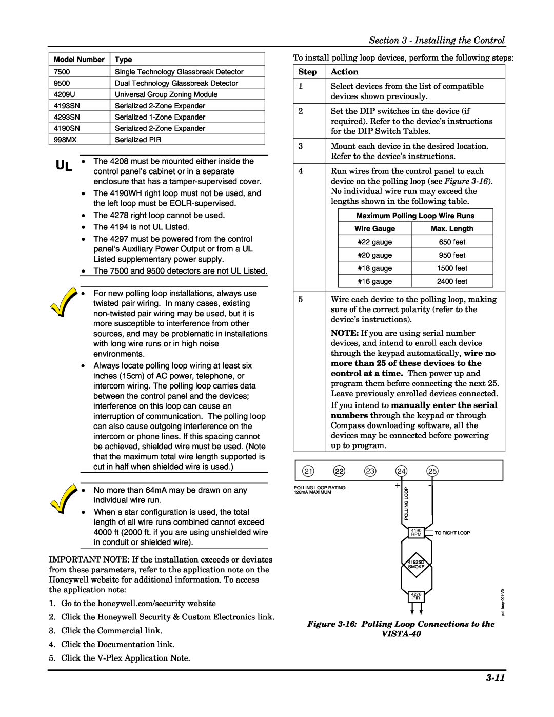
4Run wires from the control panel to each device on the polling loop (see Figure
Maximum Polling Loop Wire Runs
| Wire Gauge | Max. Length |
|
| #22 gauge | 650 feet |
|
| #20 gauge | 950 feet |
|
| #18 gauge | 1500 feet |
|
| #16 gauge | 2400 feet |
|
|
|
|
|
5Wire each device to the polling loop, making sure of the correct polarity (refer to the device’s instructions).
NOTE: If you are using serial number devices, and intend to enroll each device through the keypad automatically, wire no more than 25 of these devices to the control at a time. Then power up and program them before connecting the next 25. Leave previously enrolled devices connected. If you intend to manually enter the serial numbers through the keypad or through Compass downloading software, all the devices may be connected before powering up to program.
21 | 22 | 23 | 24 | 25 |
• No more than 64mA may be drawn on any individual wire run.
• When a star configuration is used, the total length of all wire runs combined cannot exceed 4000 ft (2000 ft. if you are using unshielded wire in conduit or shielded wire).
IMPORTANT NOTE: If the installation exceeds or deviates from these parameters, refer to the application note on the Honeywell website for additional information. To access the application note:
1. | Go to the honeywell.com/security website |
2. | Click the Honeywell Security & Custom Electronics link. |
POLLING LOOP RATING: 128mA MAXIMUM
+ LOOPPOLLING
4190 RPM
4192SD
SMOKE
4278
PIR
-
TO RIGHT LOOP
3. | Click the Commercial link. |
4. | Click the Documentation link. |
5. | Click the |