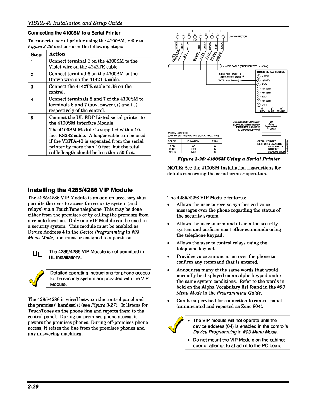
Connecting the 4100SM to a Serial Printer
To connect a serial printer using the 4100SM, refer to Figure
Step Action
1Connect terminal 1 on the 4100SM to the Violet wire on the 4142TR cable.
2Connect terminal 6 on the 4100SM to the Brown wire on the 4142TR cable.
3Connect the 4142TR cable to J8 on the control.
4Connect terminals 8 and 7 of the 4100SM to terminals 6 and 7 (aux. power (+) and
5Connect the UL EDP Listed serial printer to the 4100SM Interface Module.
The 4100SM Module is supplied with a 10- foot RS232 cable. A longer cable can be used if the
Installing the 4285/4286 VIP Module
The 4285/4286 VIP Module is an
UL | The 4285/4286 VIP Module is not permitted in |
UL installations. |
Detailed operating instructions for phone access to the security system are provided with the VIP Module.
The 4285/4286 is wired between the control panel and the premises’ handset(s) (see Figure
|
|
|
|
|
|
|
|
|
|
|
|
|
|
|
|
|
|
|
|
|
|
|
|
|
|
|
|
|
|
|
| 1 | 2 |
| 3 | 4 | 5 |
| 6 |
| 7 | 8 | 9 | J8 CONNECTOR |
|
|
|
|
|
|
| ||||||||
|
|
|
|
|
|
|
|
|
|
|
|
|
|
|
|
|
|
|
|
|
|
|
|
|
|
|
| ||
|
|
|
|
|
|
|
|
| NU |
|
|
|
|
|
|
|
|
|
|
|
|
|
|
|
|
|
|
|
|
|
| VIOLET |
| GREY |
| YELLOW |
|
| RED |
| GREEN |
| BROWN | BLUE |
| BLACK |
|
|
|
|
|
|
| ||||||
| 2 | PRINTER | DTR |
| 3 |
| GROUND | OUT | 5 |
|
| OUT | 6 | GROUND | GROUND |
|
|
|
|
|
|
| |||||||
IN |
|
|
| IN |
|
|
|
|
|
|
|
|
|
|
|
|
|
|
|
|
|
|
|
|
|
| |||
|
|
|
|
|
|
|
|
|
|
|
|
|
|
|
|
|
|
|
|
|
|
|
|
|
|
|
| ||
|
|
|
|
|
|
|
|
|
|
|
|
|
|
|
|
|
|
|
| 4142TR CABLE (SUPPLIED WITH 4100SM) |
|
|
| ||||||
|
|
|
|
|
|
|
|
|
|
|
|
|
|
|
|
|
|
|
|
|
|
|
|
|
|
|
|
| |
|
|
|
|
|
|
|
|
|
|
|
|
|
|
|
|
| To TB6 Aux. Power (+) | 4100SM SERIAL MODULE |
| ||||||||||
|
|
|
|
|
|
|
|
|
|
|
|
|
|
|
|
| 8 | + PWR |
|
|
| ||||||||
|
|
|
|
|
|
|
|
|
|
|
|
|
|
|
|
|
| (25mA current draw) |
|
|
| ||||||||
|
|
|
|
|
|
|
|
|
|
|
|
|
|
|
|
|
| To TB7 Aux. Power |
|
| 7 | - (GND) |
|
|
| ||||
|
|
|
|
|
|
|
|
|
|
|
|
|
|
|
|
|
|
|
|
|
|
| |||||||
|
|
|
|
|
|
|
|
|
|
|
|
|
|
|
|
|
|
|
|
|
|
|
|
| 6 | RXD |
|
|
|
|
|
|
|
|
|
|
|
|
|
|
|
|
|
|
|
|
|
|
|
|
|
|
|
|
|
|
| ||
|
|
|
|
|
|
|
|
|
|
|
|
|
|
|
|
|
|
|
|
|
|
| 5 | not used |
|
|
| ||
|
|
|
|
|
|
|
|
|
|
|
|
|
|
|
|
|
|
|
|
|
|
| 4 | not used |
|
|
| ||
|
|
|
|
|
|
|
|
|
|
|
|
|
|
|
|
|
|
|
|
|
|
| 3 | TXD |
|
|
| ||
|
|
|
|
|
|
|
|
|
|
|
|
|
|
|
|
|
|
|
|
|
|
| 2 | not used |
|
|
| ||
|
|
|
|
|
|
|
|
|
|
|
|
|
|
|
|
|
|
|
|
|
|
| 1 | DTR |
|
|
| ||
|
|
|
|
|
|
|
|
|
|
|
|
|
|
|
|
|
|
|
|
|
|
|
|
| RED BLUE | WHITE |
| ||
|
|
|
|
|
|
|
|
|
|
|
|
|
|
|
|
|
|
|
|
|
|
|
|
|
|
| |||
|
|
|
|
|
|
|
|
|
|
|
|
|
|
|
|
|
|
|
|
|
|
|
|
|
|
| |||
|
|
|
|
|
|
|
|
|
|
|
|
|
|
|
|
|
|
|
|
| USE GENDER CHANGER | 3M |
|
|
| ||||
|
|
|
|
|
|
|
|
|
|
|
|
|
|
|
|
|
|
|
|
| SUPPLIED WITH 4100SM | Cable |
|
|
| ||||
|
|
|
|
|
|
|
|
|
|
|
|
|
|
|
|
|
|
|
|
| IF PRINTER HAS DB25 | Supplied with |
|
| |||||
|
|
|
|
|
|
|
|
|
|
|
|
|
|
|
|
|
|
|
|
| 4100SM |
|
|
| |||||
|
|
|
|
|
|
|
|
|
|
|
|
|
|
|
|
|
|
|
|
| MALE CONNECTOR |
|
|
| |||||
|
|
|
|
|
|
|
|
|
|
|
|
|
|
|
|
|
|
|
|
|
|
|
|
| |||||
4100SM JUMPERS |
|
|
|
|
|
|
|
|
|
|
|
|
|
|
|
|
|
|
|
|
|
| |||||||
|
|
|
|
|
|
|
|
|
|
|
|
|
|
|
|
|
|
|
|
|
| ||||||||
(CUT TO SET RESPECTIVE SIGNAL FLOATING) |
|
|
|
|
|
| V0 | ||||||||||||||||||||||
|
|
|
|
|
| ||||||||||||||||||||||||
|
|
|
|
|
|
|
|
|
|
|
|
|
|
|
|
|
|
|
|
|
|
|
|
| |||||
COLOR |
|
|
|
| FUNCTION |
|
|
|
|
| PIN # |
|
|
|
|
|
|
| SERIAL PRINTER |
|
| ||||||||
|
|
|
|
|
|
|
|
|
|
|
|
|
|
|
|
|
|
|
|
|
|
|
|
| SET FOR: 8 DATA BITS | - | |||
|
|
|
|
|
|
|
|
|
|
|
|
|
|
|
|
|
|
|
|
|
|
|
|
| 011- | ||||
RED |
|
|
|
|
| CD |
|
|
|
|
|
| 8 |
|
|
|
|
|
|
|
| ||||||||
|
|
|
|
|
|
|
|
|
|
|
|
|
|
|
|
|
|
| EVEN PARITY | 4100SM | |||||||||
BLUE |
|
|
|
|
| CTS |
|
|
|
|
|
| 5 |
|
|
|
|
|
|
|
| STOP BIT | |||||||
WHITE |
|
|
|
|
| DSR |
|
|
|
|
|
| 6 |
|
|
|
|
|
|
|
| 300/1200 BAUD |
| ||||||
Figure
NOTE: See the 4100SM Installation Instructions for details concerning the serial printer operation.
The 4285/4286 VIP Module features:
•Allows the user to receive synthesized voice messages over the phone regarding the status of the security system.
•Allows the user to arm and disarm the security system and perform most other commands using the telephone keypad.
•Allows the user to control relays using the telephone keypad.
•Provides voice annunciation over the phone to confirm any command that is entered.
•Announces many of the same words that would normally be displayed on an alpha keypad under the same system conditions. Refer to the words in bold on the Alpha Vocabulary list found in the #93 Menu Mode in the Programming Guide.
•Can be supervised for connection to control panel (annunciated and reported as Zone 804).
•The VIP module will not operate until the device address (04) is enabled in the control’s Device Programming in #93 Menu Mode.
•Do not mount the VIP Module on the cabinet
door or attempt to attach it to the PC board.