System Board
This section provides additional information about the system board.
•“System Board Components” on page 80
•“System Board Architecture” on page 81
System Board Components
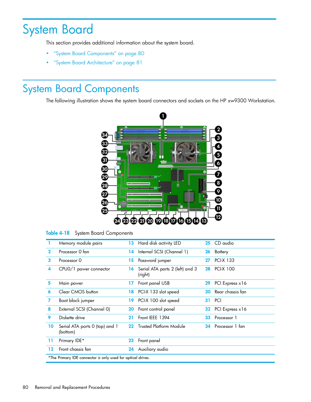
The following illustration shows the system board connectors and sockets on the HP xw9300 Workstation.
Table
1 | Memory module pairs | 13 | Hard disk activity LED | 25 | CD audio |
|
|
|
|
|
|
2 | Processor 0 fan | 14 | Internal SCSI (Channel 1) | 26 | Battery |
|
|
|
|
|
|
3 | Processor 0 | 15 | Password jumper | 27 | |
|
|
|
|
|
|
4 | CPU0/1 power connector | 16 | Serial ATA ports 2 (left) and 3 | 28 | |
|
|
| (right) |
|
|
|
|
|
|
|
|
5 | Main power | 17 | Front panel USB | 29 | PCI Express x16 |
|
|
|
|
|
|
6 | Clear CMOS button | 18 | 30 | Rear chassis fan | |
|
|
|
|
|
|
7 | Boot block jumper | 19 | 31 | PCI | |
|
|
|
|
|
|
8 | External SCSI (Channel 0) | 20 | Front control panel | 32 | PCI Express x16 |
|
|
|
|
|
|
9 | Diskette drive | 21 | Front IEEE 1394 | 33 | Processor 1 |
|
|
|
|
|
|
10 | Serial ATA ports 0 (top) and 1 | 22 | Trusted Platform Module | 34 | Processor 1 fan |
| (bottom) |
|
|
|
|
|
|
|
|
|
|
11 | Primary IDE* | 23 | Front panel |
|
|
|
|
|
|
|
|
12 | Front chassis fan | 24 | Auxiliary audio |
|
|
*The Primary IDE connector is only used for optical drives.
80 Removal and Replacement Procedures