|
|
|
| Intel® IXP45X and Intel® IXP46X Product Line of Network |
|
|
|
| Design Considerations |
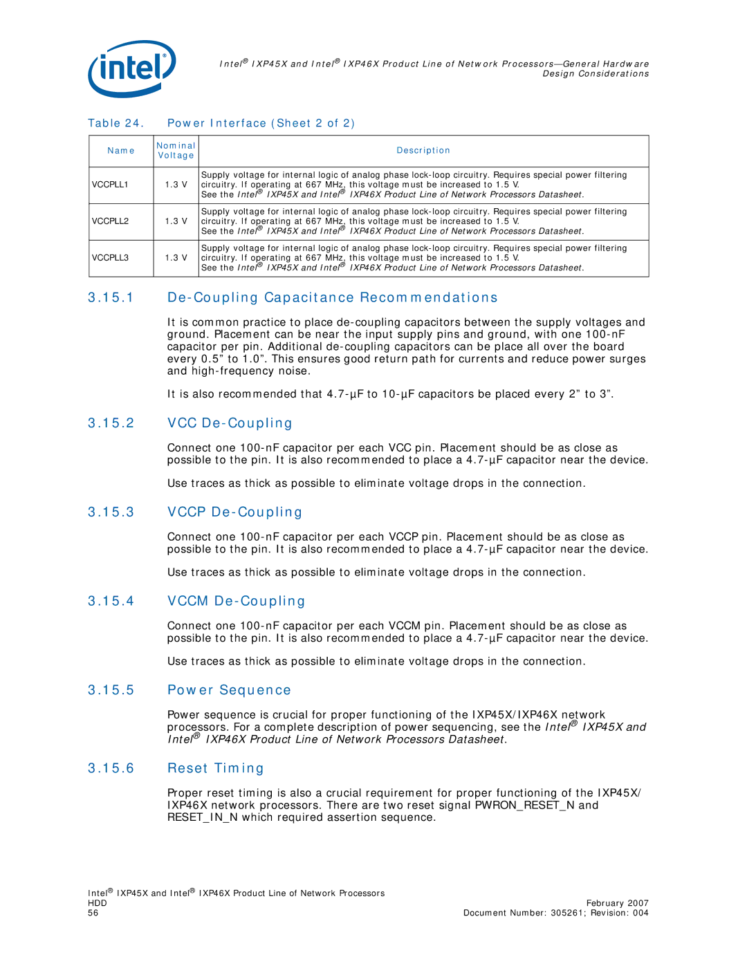
Table 24. | Power Interface (Sheet 2 of 2) | |||
|
|
|
|
|
|
| Name | Nominal | Description |
|
| Voltage | ||
|
|
|
| |
|
|
|
|
|
|
|
|
| Supply voltage for internal logic of analog phase |
VCCPLL1 | 1.3 V | circuitry. If operating at 667 MHz, this voltage must be increased to 1.5 V. | ||
|
|
|
| See the Intel® IXP45X and Intel® IXP46X Product Line of Network Processors Datasheet. |
|
|
|
| Supply voltage for internal logic of analog phase |
VCCPLL2 | 1.3 V | circuitry. If operating at 667 MHz, this voltage must be increased to 1.5 V. | ||
|
|
|
| See the Intel® IXP45X and Intel® IXP46X Product Line of Network Processors Datasheet. |
|
|
|
| Supply voltage for internal logic of analog phase |
VCCPLL3 | 1.3 V | circuitry. If operating at 667 MHz, this voltage must be increased to 1.5 V. | ||
|
|
|
| See the Intel® IXP45X and Intel® IXP46X Product Line of Network Processors Datasheet. |
3.15.1De-Coupling Capacitance Recommendations
It is common practice to place
It is also recommended that
3.15.2VCC De-Coupling
Connect one
Use traces as thick as possible to eliminate voltage drops in the connection.
3.15.3VCCP De-Coupling
Connect one
Use traces as thick as possible to eliminate voltage drops in the connection.
3.15.4VCCM De-Coupling
Connect one
Use traces as thick as possible to eliminate voltage drops in the connection.
3.15.5Power Sequence
Power sequence is crucial for proper functioning of the IXP45X/IXP46X network processors. For a complete description of power sequencing, see the Intel® IXP45X and Intel® IXP46X Product Line of Network Processors Datasheet.
3.15.6Reset Timing
Proper reset timing is also a crucial requirement for proper functioning of the IXP45X/ IXP46X network processors. There are two reset signal PWRON_RESET_N and RESET_IN_N which required assertion sequence.
Intel® IXP45X and Intel® IXP46X Product Line of Network Processors |
|
HDD | February 2007 |
56 | Document Number: 305261; Revision: 004 |