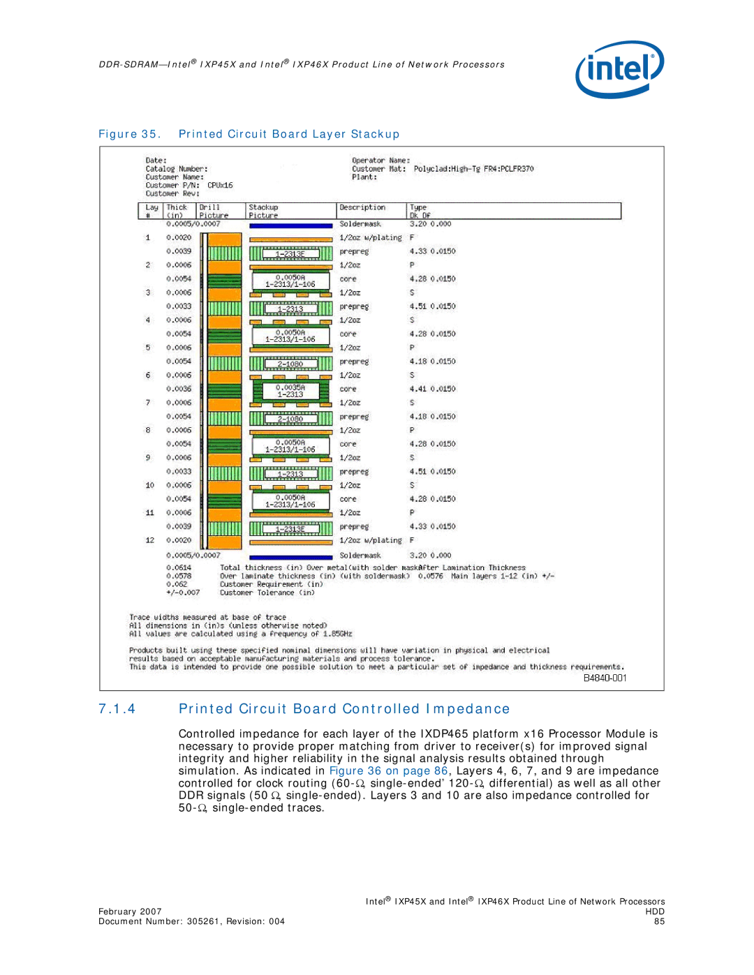
Figure 35. Printed Circuit Board Layer Stackup
7.1.4Printed Circuit Board Controlled Impedance
Controlled impedance for each layer of the IXDP465 platform x16 Processor Module is necessary to provide proper matching from driver to receiver(s) for improved signal integrity and higher reliability in the signal analysis results obtained through simulation. As indicated in Figure 36 on page 86, Layers 4, 6, 7, and 9 are impedance controlled for clock routing
| Intel® IXP45X and Intel® IXP46X Product Line of Network Processors |
February 2007 | HDD |
Document Number: 305261, Revision: 004 | 85 |
