8

7

6

5

4

3

2

1

Copyright 2002 Intel Corporation

J8

Pg. 10

U23

DC5P5V

Momentary Switches

CF_TYPE_II

Compact Flash Type II Socket

50GND2

MIC5219BM5

ADJ LDO REG

D

C

B

{3,15} SA1111_IRQ_CF_BVD1

{3,15} GFX_IRQ_CF_BVD2

{6,15} CF_GFX_RESET

R135

{13} CF_nCD1 100K

R136

{13} CF_nCD2 100K

R139 {6} CF_nIOIS16 100K

R141 {6} CF_nPWAIT 100K

C87

0.1UF

C89

0.1UF


{13}


CF_nCD2


{7,15}

VX_D10


{6}

CF_nIOIS16


{7,15}

VX_D9


{7,15}

VX_D2


{7,15}

VX_D8


R129


{7,15}

VX_D1


R130

10K


{7,15}

VX_D0


10K


{6,15}

VX_A0


{6}

CF_nPREG


{6,15}

VX_A1


CF_I2C_SDA


{6,15}

VX_A2


{6}

CF_nPWAIT


R132


{6,15}

VX_A3


1K


{7,15}

VX_A4


CF_I2C_SCL


{7,15}

VX_A5


{6,15} nNEP_REG_CS


{7,15}

VX_A6


CF_VDD


{6,15} CF_IRQ_LVL2OE


{7,15}

VX_A7


{6}


CF_nPWE


{7,15}

VX_A8


{6}


CF_nPIOW

DC3P3V


{7,15}

VX_A9


{6}


CF_nPIOR


{6}


CF_nPOE


{8}


CF_AUD


{7,15}

VX_A10


{6} CF_nPCE_2


{6} CF_nPCE_1


{7,15}

VX_D15


{7,15}

VX_D7


{7,15}

VX_D14


{7,15}

VX_D6


{7,15}

VX_D13


{7,15}

VX_D5


{7,15}

VX_D12


{7,15}

VX_D4


{7,15}

VX_D11


{7,15}

VX_D3


{13}


CF_nCD1


U25


C86


MAX3244ECAI


0.1UF


28

RS-232 XCVR


27


C88

C1+


V+


24


3


C1-


V-


DC3P3V


1

C2+


0.1UF

2


C2-


14


9


RS_TX

25nCD2

49D10

24nIOIS16

48D09

23D02

47D08

22D01

46BVD1

21D00

45BVD2

20A00

44nREG

19A01

43nINPACK

18A02

42nWAIT

17A03

41RESET

16A04

40nVS2

15A05

39nCSE

14A06

38VCC2

13VCC1

37IREQ

12A07

36nWE

11A08

35nIOWR

10A09

34nIORD

9nOE

33nVS1

8A10

32nCE2

7nCE1

31D15

6D07

30D14

5D06

29D13

4D05

28D12

3D04

27D11

2D03

26nCD1

1GND1

{13} CF_PWR

{3,8,11,12,13,14} VBATT

DC3P3V

RS_DCD

{3,6,11,13} JTAG_TCK RS_TX

R122

0

RS_RTS

RS_CTS

RS_DTR

RS_DSR

{12,15} IN_PWR

1

500ma

VOUT

5


DC3P3V


S2


VIN


2

GND


R128 R126


1.5K 953


1

S

2


GPIO_0

{3,15}


4


3


3


4


R127

100K


EN

ADJ


LGAA


DC3P3V


S3


U24


MIC5219-3.3BM5


1

S

2


GPIO_32

{3}


4


3


R131

100K


3.3V LDO REG


CF_VDD


1

500ma

VOUT

5


VIN


2

GND


1


DC3P3V


S4


4.7UF

+


C85


3

EN

BYP

4


1

S

2


GPIO_17

{3}


4


3


LG33


2


R133

100K


DC3P3V


S5


1

S

2

R15


GPIO_22

{2,11}

J9

Base Station Connector


4


3

0


R134

100K


20


Three Position Switch


19


18


17


R138


{2,14}

GPIO_21


100K


16


15


RS_RI


14


13


R140


R16


SA_nWE

{2,4,5,6,7}


0


1.5K


12


11


DC3P3V


10


9


RS_RX


S6


8


7


4

5

6


CCW


R142


6


5


nRESET_IN {3,11,15}


0


4


3


DNI


PUSH


2


1


JTAG_TMS

{3,6,11,13}


CW


22


CPLD1_TDI

{6,11}


1

2

3


21


R144


SA_TDO

{3,11}


R17


75


0


R153

0


{2,14}

GPIO_20


{2,14}

GPIO_19


D

C

B

A

{2,15} SA_FF_TXD {2} SA_FF_RTS {2} SA_FF_DTR

{2,15} SA_FF_RXD {2} SA_FF_DCD {2} SA_FF_DSR

{2} SA_FF_RI {2} SA_FF_CTS

13

T1 IN

T1OUT

10

RS_RTS

T2 IN

T2OUT

12

11

RS_DTR

T3 IN

T3OUT


19

R1OUT

R1 IN

4

RS_RX

18

5

RS_DCD

R2OUT

R2 IN

17

6

RS_DSR

R3OUT

R3 IN

16

7

RS_RI

R4OUT

R4 IN

15

8

RS_CTS

R5OUT

R5 IN


U26


DC3P3V

R145

100K

R146

100K


MAX4542


V+

2


{2,12,15} SA_I2C_SCL

8

COM_1


7

IN_1

NC_1

1


CF_I2C_SCL


A


20

R2OUTB

INVLD

21


22

26

{6} RS232_ON

FORCEOFF

VCC

23

25


FORCEON

GND


C90

0.1UF

RS232_VALID {3}


4


5

CF_I2C_SDA


{2,12,15}

SA_I2C_SDA

COM_2

NC_2


{3}

SA_I2C_ENAB

3

IN_2


PXA250 Processor Reference Design


GND

6

Size

Rev


AAAF


B

2.07


Date:

Tuesday, February 05, 2002

Sheet

10

of

16

8

7

6

5

4

3

2


1


Page 115
Image 115
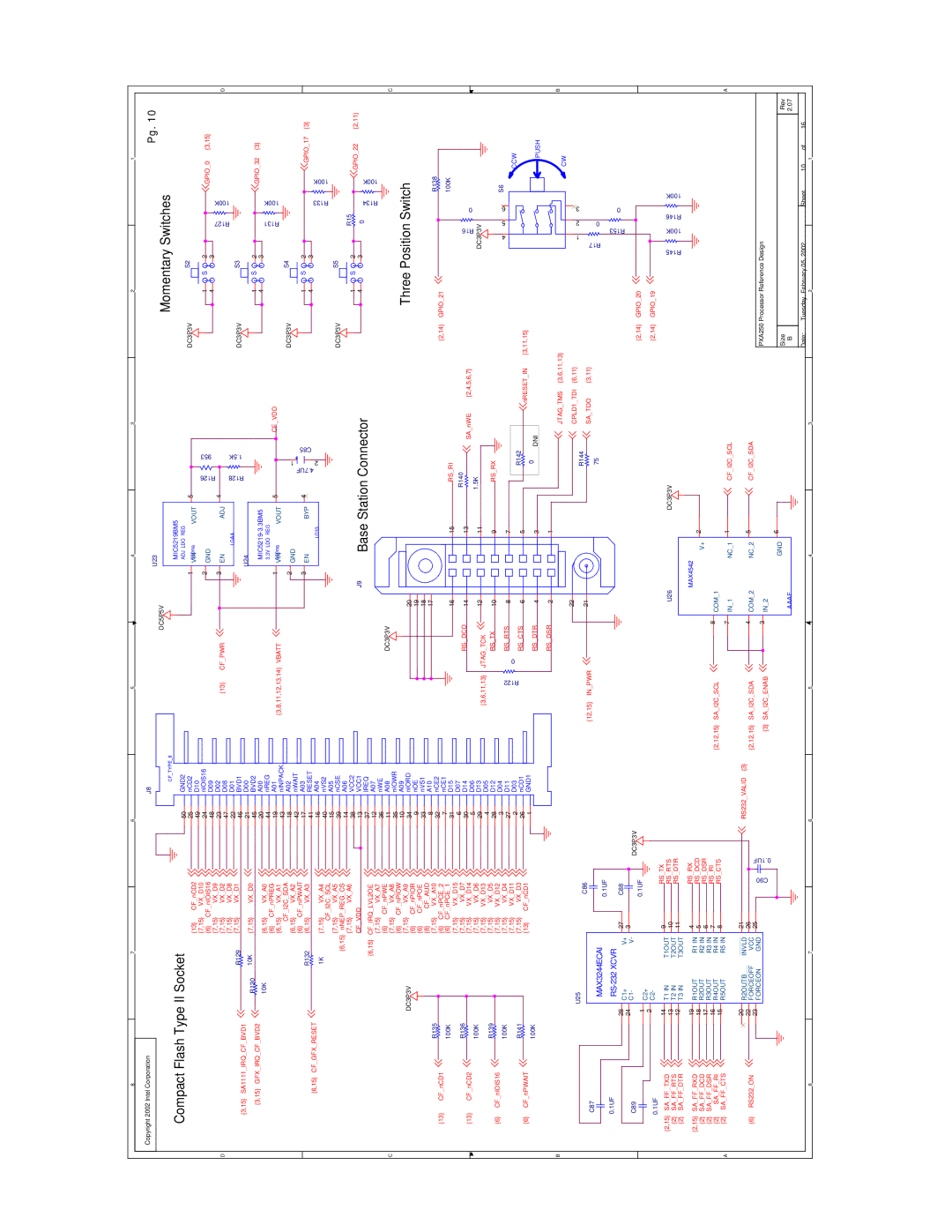
Intel PXA250 and PXA210 manual Momentary Switches

PXA250 and PXA210 specifications

The Intel PXA250 and PXA210 processors, part of the Intel XScale architecture, were introduced in the early 2000s, targeting mobile and embedded applications. They are known for their low power consumption, high performance, and advanced multimedia capabilities, making them suitable for a wide range of devices, including PDAs, smartphones, and other portable computing devices.

The PXA250, which operates at clock speeds ranging from 400 MHz to 624 MHz, features a superscalar architecture that allows it to issue multiple instructions per clock cycle. This enhances the overall performance for demanding applications while maintaining low power usage. It supports a variety of peripheral interfaces, including USB, Ethernet, and various memory types, which contributes to its versatility in different product designs.

One of the key technologies in the PXA250 is the integrated Intel Smart Repeat Technology, which optimizes data processing, thereby reducing the amount of power consumed during operation. This feature is particularly important for battery-powered devices, as it extends the overall battery life, allowing for longer usage times in mobile environments. Additionally, the PXA250 includes a dedicated graphics acceleration unit, which enables enhanced graphics and multimedia performance suited to modern applications at the time.

In contrast, the PXA210 is a more entry-level processor, aimed at cost-sensitive applications. Operating at lower clock speeds, typically around 200 MHz to 400 MHz, it forgoes some of the advanced performance features of the PXA250 while still offering a good balance of performance and power efficiency. The PXA210 is less complex, making it suitable for simpler devices that do not require the extensive capabilities of the PXA250.

Both processors utilize the Intel XScale architecture, which is based on the ARM instruction set. They are built on a 0.13-micron process technology, enabling higher density and lower power consumption compared to their predecessors. With integrated memory controllers and bus interfaces, they facilitate efficient data handling and connectivity options.

In summary, both the Intel PXA250 and PXA210 processors played a crucial role in the evolution of mobile computing by providing powerful processing capabilities with energy efficiency. Their features and technologies enabled device manufacturers to create innovative products that catered to the growing demand for portable devices during that era.