SA-1110/Applications Processor Migration

Table A-1. PXA250 Boot Select Options (Sheet 2 of 2)


Boot Select Pins


Boot Location


2


1


0


0


1


1

Synchronous 16-bit Flash


1


0


0

(1)

Synchronous 32-bit Mask ROM (64 Mbit)


(2)

Synchronous 16-bit Mask ROM = 32bits (32 Mbit)


1


0


1

(1)

Synchronous 16-bit Mask ROM (64 Mbit)


1


1


0

(2)

Synchronous 16-bit Mask ROM = 32bits (64 Mbit)


1


1


1

(1)

Synchronous 16-bit Mask ROM (32 Mbit)


The power fault (VDD_FAULT) and battery fault (BATT_FAULT) pins that drive the SA-1110 sleep mode are negated with respect to the PXA250 applications processor. You must invert these signals or change the design to make sure that these signals are negated with respect to the SA- 1110 design.

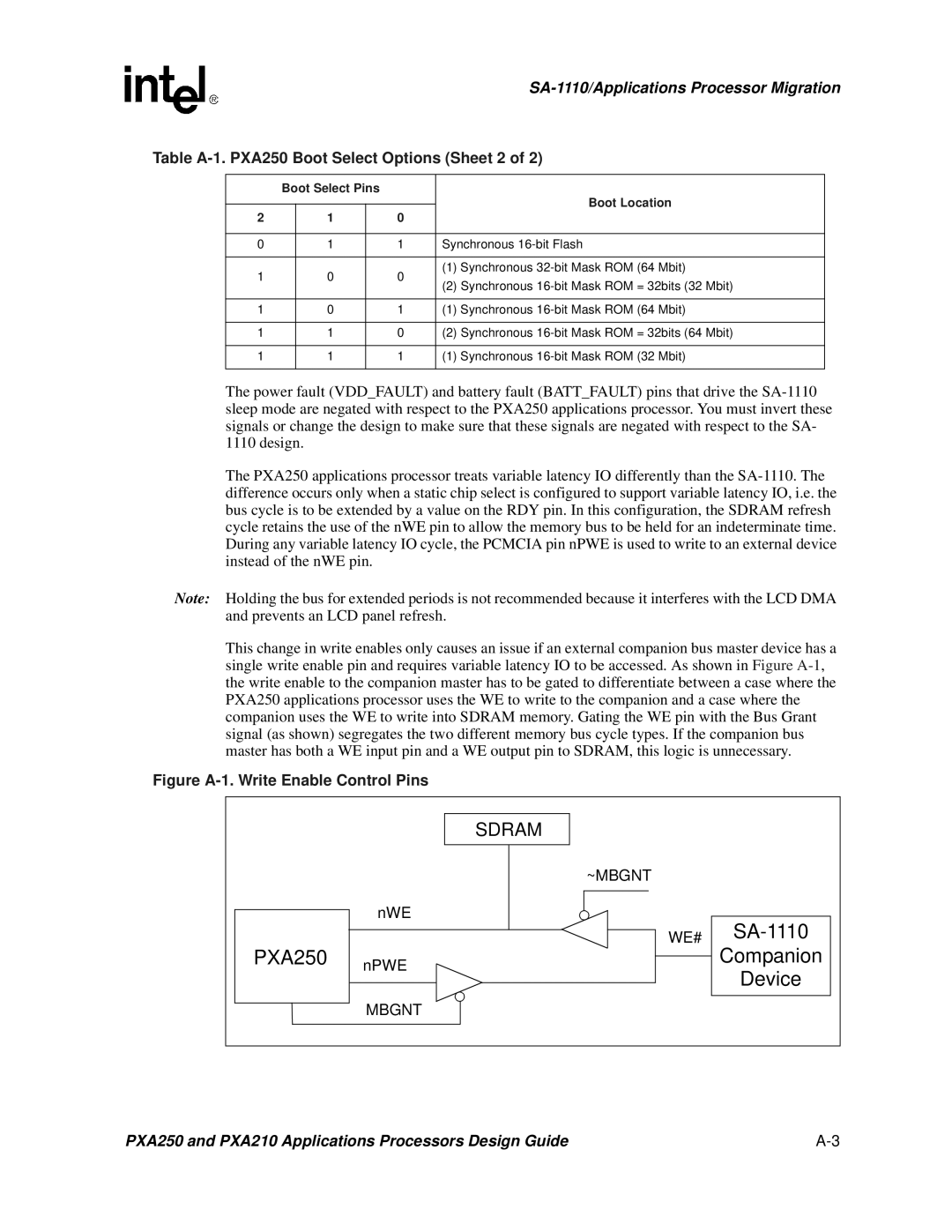
The PXA250 applications processor treats variable latency IO differently than the SA-1110. The difference occurs only when a static chip select is configured to support variable latency IO, i.e. the bus cycle is to be extended by a value on the RDY pin. In this configuration, the SDRAM refresh cycle retains the use of the nWE pin to allow the memory bus to be held for an indeterminate time. During any variable latency IO cycle, the PCMCIA pin nPWE is used to write to an external device instead of the nWE pin.

Note: Holding the bus for extended periods is not recommended because it interferes with the LCD DMA and prevents an LCD panel refresh.

This change in write enables only causes an issue if an external companion bus master device has a single write enable pin and requires variable latency IO to be accessed. As shown in Figure A-1, the write enable to the companion master has to be gated to differentiate between a case where the PXA250 applications processor uses the WE to write to the companion and a case where the companion uses the WE to write into SDRAM memory. Gating the WE pin with the Bus Grant signal (as shown) segregates the two different memory bus cycle types. If the companion bus master has both a WE input pin and a WE output pin to SDRAM, this logic is unnecessary.

Figure A-1. Write Enable Control Pins


SDRAM


~MBGNT


nWE

SA-1110


WE#

PXA250

nPWE

Companion


Device


MBGNT


PXA250 and PXA210 Applications Processors Design Guide

A-3

Page 97
Image 97
Intel PXA250 and PXA210 manual Table A-1. PXA250 Boot Select Options Sheet 2, Figure A-1. Write Enable Control Pins

PXA250 and PXA210 specifications

The Intel PXA250 and PXA210 processors, part of the Intel XScale architecture, were introduced in the early 2000s, targeting mobile and embedded applications. They are known for their low power consumption, high performance, and advanced multimedia capabilities, making them suitable for a wide range of devices, including PDAs, smartphones, and other portable computing devices.

The PXA250, which operates at clock speeds ranging from 400 MHz to 624 MHz, features a superscalar architecture that allows it to issue multiple instructions per clock cycle. This enhances the overall performance for demanding applications while maintaining low power usage. It supports a variety of peripheral interfaces, including USB, Ethernet, and various memory types, which contributes to its versatility in different product designs.

One of the key technologies in the PXA250 is the integrated Intel Smart Repeat Technology, which optimizes data processing, thereby reducing the amount of power consumed during operation. This feature is particularly important for battery-powered devices, as it extends the overall battery life, allowing for longer usage times in mobile environments. Additionally, the PXA250 includes a dedicated graphics acceleration unit, which enables enhanced graphics and multimedia performance suited to modern applications at the time.

In contrast, the PXA210 is a more entry-level processor, aimed at cost-sensitive applications. Operating at lower clock speeds, typically around 200 MHz to 400 MHz, it forgoes some of the advanced performance features of the PXA250 while still offering a good balance of performance and power efficiency. The PXA210 is less complex, making it suitable for simpler devices that do not require the extensive capabilities of the PXA250.

Both processors utilize the Intel XScale architecture, which is based on the ARM instruction set. They are built on a 0.13-micron process technology, enabling higher density and lower power consumption compared to their predecessors. With integrated memory controllers and bus interfaces, they facilitate efficient data handling and connectivity options.

In summary, both the Intel PXA250 and PXA210 processors played a crucial role in the evolution of mobile computing by providing powerful processing capabilities with energy efficiency. Their features and technologies enabled device manufacturers to create innovative products that catered to the growing demand for portable devices during that era.