System Memory Interface

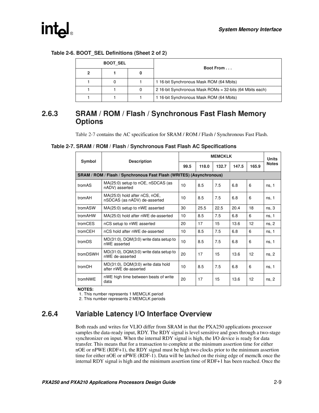
Table 2-6. BOOT_SEL Definitions (Sheet 2 of 2)


BOOT_SEL


Boot From . . .


2

1

0


1

0

1

1 16-bit Synchronous Mask ROM (64 Mbits)


1

1

0

2 16-bit Synchronous Mask ROMs = 32-bits (64 Mbits each)


1

1

1

1 16-bit Synchronous Mask ROM (64 Mbits)


2.6.3SRAM / ROM / Flash / Synchronous Fast Flash Memory Options

Table 2-7contains the AC specification for SRAM / ROM / Flash / Synchronous Fast Flash.

Table 2-7. SRAM / ROM / Flash / Synchronous Fast Flash AC Specifications


MEMCKLK


Units

Symbol

Description


99.5

118.0


132.7


147.5

165.9

Notes


SRAM / ROM / Flash / Synchronous Fast Flash (WRITES) (Asynchronous)


tromAS

MA(25:0) setup to nOE, nSDCAS (as

10

8.5


7.5


6.8

6

ns, 1

nADV) asserted


tromAH

MA(25:0) hold after nCS, nOE,

10

8.5


7.5


6.8

6

ns, 1

nSDCAS (as nADV) de-asserted


tromASW

MA(25:0) setup to nWE asserted

30

25.5


22.5


20.4

18

ns, 3


tromAHW

MA(25:0) hold after nWE de-asserted

10

8.5


7.5


6.8

6

ns, 1


tromCES

nCS setup to nWE asserted

20

17


15


13.6

12

ns, 2


tromCEH

nCS hold after nWE de-asserted

10

8.5


7.5


6.8

6

ns, 1


tromDS

MD(31:0), DQM(3:0) write data setup to

10

8.5


7.5


6.8

6

ns, 1

nWE asserted


tromDSWH

MD(31:0), DQM(3:0) write data setup to

20

17


15


13.6

12

ns, 2

nWE de-asserted


tromDH

MD(31:0), DQM(3:0) write data hold

10

8.5


7.5


6.8

6

ns, 1

after nWE de-asserted


tromNWE

nWE high time between beats of write

20

17


15


13.6

12

ns, 2

data


NOTES:


1.This number represents 1 MEMCLK period

2.This number represents 2 MEMCLK periods

2.6.4Variable Latency I/O Interface Overview

Both reads and writes for VLIO differ from SRAM in that the PXA250 applications processor samples the data-ready input, RDY. The RDY signal is level sensitive and goes through a two-stage synchronizer on input. When the internal RDY signal is high, the I/O device is ready for data transfer. This means that for a transaction to complete at the minimum assertion time for either nOE or nPWE (RDF+1), the RDY signal must be high two clocks prior to the minimum assertion time for either nOE or nPWE (RDF-1). Data will be latched on the rising edge of memclk once the internal RDY signal is high and the minimum assertion time of RDF+1 has been reached. Once the

PXA250 and PXA210 Applications Processors Design Guide

2-9

Page 35
Image 35
Intel PXA250 and PXA210 Sram / ROM / Flash / Synchronous Fast Flash Memory Options, Bootsel Definitions Sheet 2, Units

PXA250 and PXA210 specifications

The Intel PXA250 and PXA210 processors, part of the Intel XScale architecture, were introduced in the early 2000s, targeting mobile and embedded applications. They are known for their low power consumption, high performance, and advanced multimedia capabilities, making them suitable for a wide range of devices, including PDAs, smartphones, and other portable computing devices.

The PXA250, which operates at clock speeds ranging from 400 MHz to 624 MHz, features a superscalar architecture that allows it to issue multiple instructions per clock cycle. This enhances the overall performance for demanding applications while maintaining low power usage. It supports a variety of peripheral interfaces, including USB, Ethernet, and various memory types, which contributes to its versatility in different product designs.

One of the key technologies in the PXA250 is the integrated Intel Smart Repeat Technology, which optimizes data processing, thereby reducing the amount of power consumed during operation. This feature is particularly important for battery-powered devices, as it extends the overall battery life, allowing for longer usage times in mobile environments. Additionally, the PXA250 includes a dedicated graphics acceleration unit, which enables enhanced graphics and multimedia performance suited to modern applications at the time.

In contrast, the PXA210 is a more entry-level processor, aimed at cost-sensitive applications. Operating at lower clock speeds, typically around 200 MHz to 400 MHz, it forgoes some of the advanced performance features of the PXA250 while still offering a good balance of performance and power efficiency. The PXA210 is less complex, making it suitable for simpler devices that do not require the extensive capabilities of the PXA250.

Both processors utilize the Intel XScale architecture, which is based on the ARM instruction set. They are built on a 0.13-micron process technology, enabling higher density and lower power consumption compared to their predecessors. With integrated memory controllers and bus interfaces, they facilitate efficient data handling and connectivity options.

In summary, both the Intel PXA250 and PXA210 processors played a crucial role in the evolution of mobile computing by providing powerful processing capabilities with energy efficiency. Their features and technologies enabled device manufacturers to create innovative products that catered to the growing demand for portable devices during that era.