Return to Section TOC
Return to Section TOC
Return to Master TOC
Return to Master TOC
TROUBLESHOOTING & REPAIR
DIODE REMOVAL AND REPLACEMENT (continued)
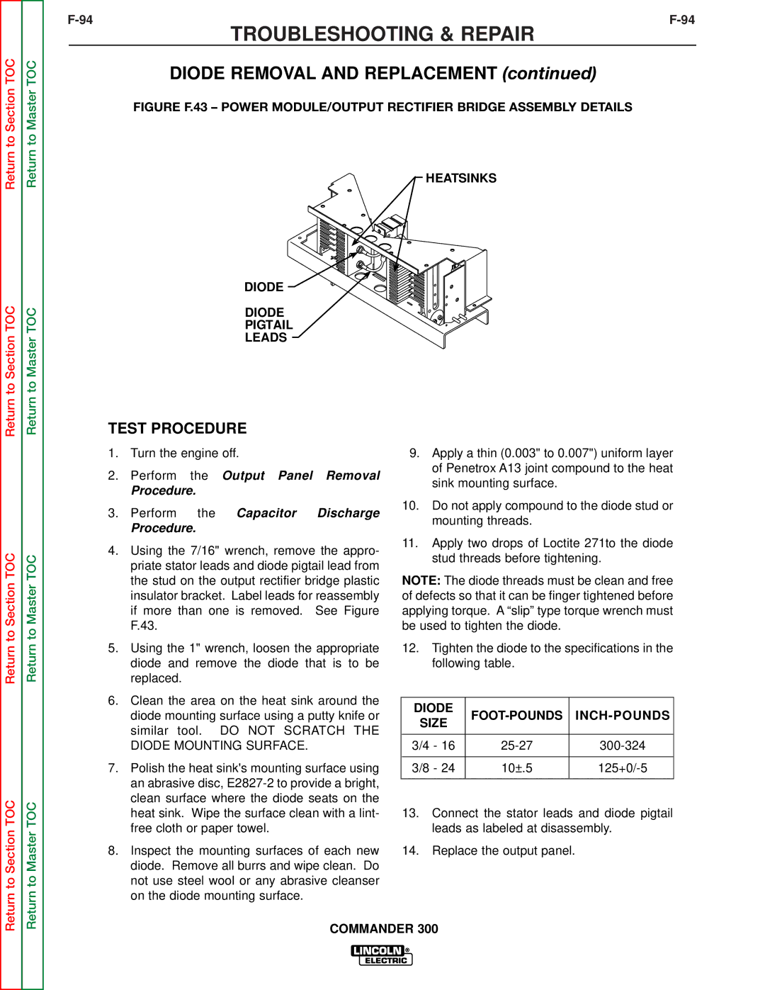
FIGURE F.43 – POWER MODULE/OUTPUT RECTIFIER BRIDGE ASSEMBLY DETAILS
HEATSINKS
DIODE
DIODE
PIGTAIL
LEADS
Return to Section TOC
Return to Section TOC
Return to Master TOC
Return to Master TOC
TEST PROCEDURE
1.Turn the engine off.
2.Perform the Output Panel Removal
Procedure.
3.Perform the Capacitor Discharge
Procedure.
4.Using the 7/16" wrench, remove the appro- priate stator leads and diode pigtail lead from the stud on the output rectifier bridge plastic insulator bracket. Label leads for reassembly if more than one is removed. See Figure F.43.
5.Using the 1" wrench, loosen the appropriate diode and remove the diode that is to be replaced.
6.Clean the area on the heat sink around the diode mounting surface using a putty knife or similar tool. DO NOT SCRATCH THE DIODE MOUNTING SURFACE.
7.Polish the heat sink's mounting surface using an abrasive disc,
8.Inspect the mounting surfaces of each new diode. Remove all burrs and wipe clean. Do not use steel wool or any abrasive cleanser on the diode mounting surface.
9.Apply a thin (0.003" to 0.007") uniform layer of Penetrox A13 joint compound to the heat sink mounting surface.
10.Do not apply compound to the diode stud or mounting threads.
11.Apply two drops of Loctite 271to the diode stud threads before tightening.
NOTE: The diode threads must be clean and free of defects so that it can be finger tightened before applying torque. A “slip” type torque wrench must be used to tighten the diode.
12.Tighten the diode to the specifications in the following table.
DIODE |
|
| |
SIZE | |||
|
| ||
|
|
| |
3/4 - 16 | |||
|
|
| |
3/8 - 24 | 10±.5 | ||
|
|
|
13.Connect the stator leads and diode pigtail leads as labeled at disassembly.
14.Replace the output panel.