ACCESSORIES
Return to Master TOC
CONNECTION OF THE
1.Shut the welder off.
2.Connect the electrode cable from the
NOTE: Welding cable must be sized for current and duty cycle of application.
CAUTION
Any increase of the high idle engine RPM by changing the governor setting or overriding the throttle linkage will cause an increase in the AC auxiliary voltage. If this voltage goes over 140 volts, wire feeder control cir- cuits may be damaged. The engine governor setting is preset at the
Return to Master TOC
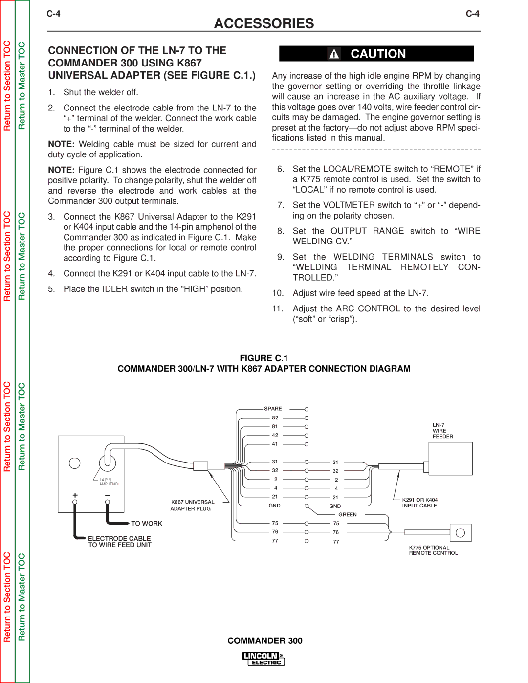
NOTE: Figure C.1 shows the electrode connected for positive polarity. To change polarity, shut the welder off and reverse the electrode and work cables at the Commander 300 output terminals.
3.Connect the K867 Universal Adapter to the K291 or K404 input cable and the
4.Connect the K291 or K404 input cable to the
5.Place the IDLER switch in the “HIGH” position.
6.Set the LOCAL/REMOTE switch to “REMOTE” if a K775 remote control is used. Set the switch to “LOCAL” if no remote control is used.
7.Set the VOLTMETER switch to “+” or
8.Set the OUTPUT RANGE switch to “WIRE
WELDING CV.”
9.Set the WELDING TERMINALS switch to
“WELDING TERMINAL REMOTELY CON- TROLLED.”
10.Adjust wire feed speed at the
11.Adjust the ARC CONTROL to the desired level (“soft” or “crisp”).
Return to Section TOC
Return to Section TOC
FIGURE C.1
COMMANDER 300/LN-7 WITH K867 ADAPTER CONNECTION DIAGRAM
Return to Section TOC
Return to Master TOC
14 PIN AMPHENOL
+–
SPARE |
| |
82 |
| |
81 | ||
WIRE | ||
42 | ||
FEEDER |
| 41 |
|
| |
| 31 | 31 |
| |
| 32 | 32 |
| |
| 2 | 2 |
| |
| 4 | 4 |
| |
K867 UNIVERSAL | 21 | 21 | K291 OR K404 | |
GND |
| |||
GND | INPUT CABLE | |||
ADAPTER PLUG | ||||
|
|
|
GREEN
Return to Section TOC
Return to Master TOC
TO WORK | 75 | 75 | |
ELECTRODE CABLE | 76 | 76 | |
77 | 77 | ||
TO WIRE FEED UNIT | |||
| K775 OPTIONAL | ||
|
|
REMOTE CONTROL