Return to Section TOC
Return to Section TOC
Section TOC
Return to Master TOC
Return to Master TOC
Master TOC
TROUBLESHOOTING & REPAIR
CASE COVER REMOVAL AND REPLACEMENT PROCEDURE (continued)
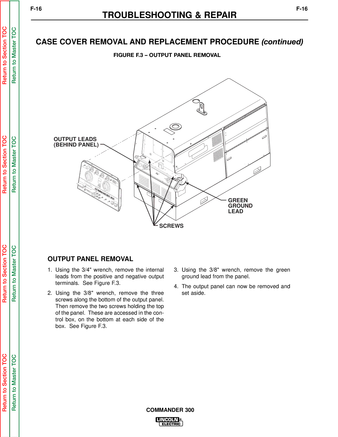
FIGURE F.3 – OUTPUT PANEL REMOVAL
OUTPUT LEADS (BEHIND PANEL)
GREEN
GROUND
LEAD
SCREWS
OUTPUT PANEL REMOVAL
Return to
Return to
1.Using the 3/4" wrench, remove the internal leads from the positive and negative output terminals. See Figure F.3.
2.Using the 3/8" wrench, remove the three screws along the bottom of the output panel. Then remove the two screws holding the top of the panel. These are accessed in the con- trol box, on the bottom at each side of the box. See Figure F.3.
3.Using the 3/8" wrench, remove the green ground lead from the panel.
4.The output panel can now be removed and set aside.
Return to Section TOC
Return to Master TOC