Return to Section TOC
Return to Section TOC
Return to Section TOC
Return to Master TOC
Return to Master TOC
Return to Master TOC
TROUBLESHOOTING & REPAIR
STATOR/ROTOR REMOVAL AND REPLACEMENT (continued)
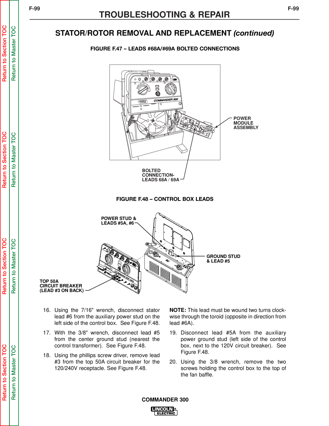
FIGURE F.47 – LEADS #68A/#69A BOLTED CONNECTIONS
POWER
MODULE
ASSEMBLY
BOLTED
CONNECTION-
LEADS 68A / 69A
FIGURE F.48 – CONTROL BOX LEADS
POWER STUD &
LEADS #5A, #6
![]()
![]() GROUND STUD & LEAD #5
GROUND STUD & LEAD #5
TOP 50A
CIRCUIT BREAKER (LEAD #3 ON BACK)
Return to Section TOC
Return to Master TOC
16.Using the 7/16" wrench, disconnect stator lead #6 from the auxiliary power stud on the left side of the control box. See Figure F.48.
17.With the 3/8" wrench, disconnect lead #5 from the center ground stud (nearest the control transformer). See Figure F.48.
18.Using the phillips screw driver, remove lead #3 from the top 50A circuit breaker for the 120/240V receptacle. See Figure F.48.
NOTE: This lead must be wound two turns clock- wise through the toroid (opposite in direction from lead #6A).
19.Disconnect lead #5A from the auxiliary power ground stud (left side of the control box, next to the 120V circuit breaker). See Figure F.48.
20.Using the 3/8 wrench, remove the two screws holding the control box to the top of the fan baffle.