Return to Section TOC
Return to Section TOC
Return to Master TOC
Return to Master TOC
THEORY OF OPERATION
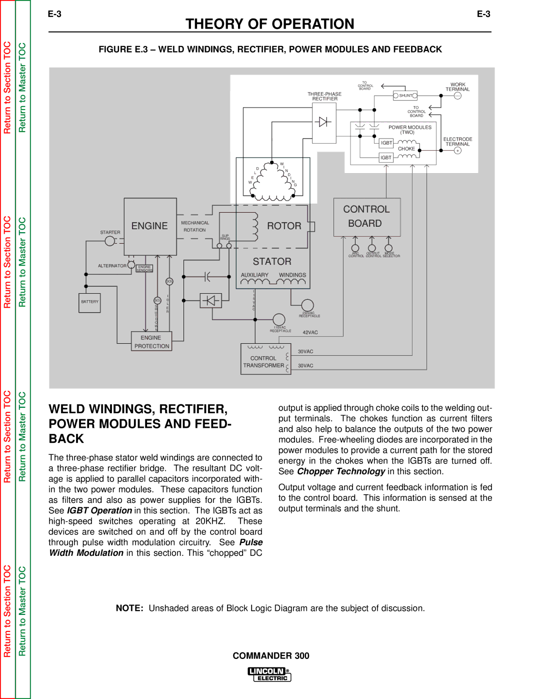
FIGURE E.3 – WELD WINDINGS, RECTIFIER, POWER MODULES AND FEEDBACK
| TO | WORK |
| CONTROL | |
| BOARD | TERMINAL |
SHUNT | __ | |
RECTIFIER |
|
|
| TO |
|
| CONTROL |
|
| BOARD |
|
| POWER MODULES |
|
| (TWO) |
|
| IGBT | ELECTRODE |
| TERMINAL | |
| CHOKE | + |
|
|
|
|
|
|
| IGBT |
|
|
|
|
| W |
|
|
|
|
|
| D | I |
|
|
|
|
|
| N |
|
| |
|
|
|
| L |
|
| |
|
|
|
| D |
|
| |
|
|
| E |
|
| ||
|
|
| I | N |
| ||
|
|
| W |
|
|
| |
|
|
|
|
|
| G |
|
|
|
|
|
|
|
| CONTROL |
| ENGINE | ROTATION | ROTOR | BOARD | |||
|
|
| MECHANICAL |
|
|
|
|
STARTER |
|
| SLIP |
|
|
|
|
|
|
|
|
|
|
| |
|
|
| RINGS |
|
|
|
|
|
|
|
|
|
|
| ARC OUTPUT MODE |
|
|
|
| STATOR |
| CONTROL CONTROL SELECTOR | |
ALTERNATOR | ENGINE |
|
|
|
| ||
|
|
|
|
|
| ||
| SENSORS |
| AUXILIARY | WINDINGS |
| ||
|
|
|
| ||||
|
| SOL |
|
|
|
|
|
|
|
|
| 1 |
|
|
|
|
| I |
| 1 |
|
|
|
BATTERY | SOL | D |
| 5 |
|
|
|
| V |
|
|
| |||
| L |
|
|
|
| ||
| S |
| A |
|
|
| |
| E |
|
|
|
| ||
| H |
| C |
|
|
| |
| R |
|
|
|
| ||
| U |
|
|
| 230VAC |
| |
| T |
|
|
|
| RECEPTACLE |
|
| D |
|
|
|
|
|
|
| O |
|
|
|
|
|
|
| W |
|
|
| 115VAC |
|
|
| N |
|
|
|
|
| |
|
|
|
| RECEPTACLE | 42VAC |
| |
| ENGINE |
|
|
|
|
| |
|
|
|
|
|
|
| |
| PROTECTION |
|
|
| 30VAC |
| |
|
|
|
|
|
|
| |
|
|
| CONTROL |
|
| ||
|
|
| TRANSFORMER | 30VAC |
| ||
Return to Section TOC
Return to Master TOC
WELD WINDINGS, RECTIFIER, POWER MODULES AND FEED- BACK
The
output is applied through choke coils to the welding out- put terminals. The chokes function as current filters and also help to balance the outputs of the two power modules.
Output voltage and current feedback information is fed to the control board. This information is sensed at the output terminals and the shunt.
Return to Section TOC
Return to Master TOC
NOTE: Unshaded areas of Block Logic Diagram are the subject of discussion.