TROUBLESHOOTING & REPAIR
TOC | TOC |
|
| CONTROL INPUT TEST (continued) |
| |||
to Section | to Master |
|
|
|
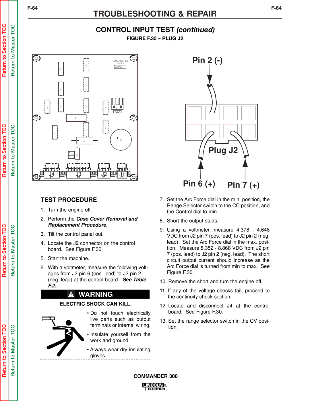
| FIGURE F.30 – PLUG J2 |
| |
|
|
|
|
| Pin 2 |
| ||
Return | Return |
|
|
| COMMANDER 300 |
| ||
| X18 |
| CONTROL |
|
| |||
X13 |
|
|
|
| ||||
|
|
|
|
| ||||
|
|
| X2 |
|
|
|
|
|
|
| X12 |
|
|
|
|
|
|
| X11 | X10 | X4 | X19 | Q1 |
|
|
|
|
|
| C54 |
|
|
|
|
|
TOC | TOC | X8 | X1 | X5 |
|
|
|
|
Section | Master |
| C1 |
| C25 |
| Plug J2 | |
to | to |
| C2 |
|
|
|
|
|
Return | Return | J4 | J3 | J2 | J1 |
|
|
|
|
|
|
|
|
|
| Pin 6 (+) | Pin 7 (+) |
|
| TEST PROCEDURE |
|
|
|
| 7. Set the Arc Force dial in the min. position, the | ||||
|
| 1. Turn the engine off. |
|
|
|
| Range Selector switch to the CC position, and | ||||
|
|
|
|
|
| the Control dial to min. | |||||
|
|
|
|
|
|
|
|
|
|
| |
|
| 2. Perform the Case Cover Removal and | 8. Short the output studs. | ||||||||
TOC |
|
|
| Replacement Procedure. |
|
|
| ||||
TOC |
|
|
|
|
| 9. Using a voltmeter, measure 4.378 - 4.648 | |||||
3. Tilt the control panel out. |
|
|
| ||||||||
|
|
|
|
| |||||||
Section | Master |
|
|
| VDC from J2 pin 7 (pos. lead) to J2 pin 2 (neg. | ||||||
|
|
|
|
|
|
|
|
| |||
4. | Locate the J2 connector on the control | lead). Set the Arc Force dial in the max. posi- | |||||||||
|
|
|
| board. See Figure F.30. |
|
|
| tion. Measure 8.352 - 8.868 VDC from J2 pin | |||
to | to | 5. | Start the machine. |
|
|
|
| 7 (pos. lead) to J2 pin 2 (neg. lead). The short | |||
|
|
|
| circuit output current should increase as the | |||||||
Return | Return |
|
|
|
|
|
|
|
|
| |
6. | With a voltmeter, measure the following volt- | Arc Force dial is turned from min to max. See | |||||||||
|
|
|
| ages from J2 pin 6 (pos. lead) to J2 pin 2 | Figure F.30. | ||||||
|
|
|
| (neg. lead) at the control board. See Table | 10. Remove the short and turn the engine off. | ||||||
|
|
|
| F.2. |
|
|
|
| |||
|
|
|
|
|
|
|
| 11. If any of the voltage checks fail, proceed to | |||
|
|
|
|
|
|
|
|
|
|
| |
|
|
|
|
|
| WARNING |
|
|
| ||
|
|
|
|
|
|
|
|
| the continuity check section. | ||
|
|
|
| ELECTRIC SHOCK CAN KILL. | 12. Locate and disconnect J4 at the control | ||||||
|
|
|
|
|
|
|
|
|
|
| |
|
|
|
|
|
| • Do | not touch | electrically | board. See Figure F.30. | ||
|
|
|
|
|
| live | parts such | as output | 13. Set the range selector switch in the CV posi- | ||
TOC | TOC |
|
|
|
| terminals or internal wiring. | |||||
|
|
|
| tion. | |||||||
|
|
|
|
|
|
|
|
| |||
|
|
|
|
|
|
|
|
|
|
| |
Section | Master |
|
|
|
| • Insulate yourself from the |
| ||||
|
|
|
| work and ground. |
| ||||||
|
|
|
|
|
|
| |||||
|
|
|
|
|
| • Always wear dry insulating |
| ||||
Return to | Return to |
|
|
|
| gloves. |
|
|
|
| |
|
|
|
|
|
|
|
|
|
| ||
|
|
|
|
|
| COMMANDER 300 | |||||
|
|
|
|
|
|
|
| ||||