Return to Section TOC
Return to Section TOC
Return to Section TOC
Return to Master TOC
Return to Master TOC
Return to Master TOC
| |||
| TROUBLESHOOTING & REPAIR | ||
| CONTROL INPUT TEST (continued) |
| |
|
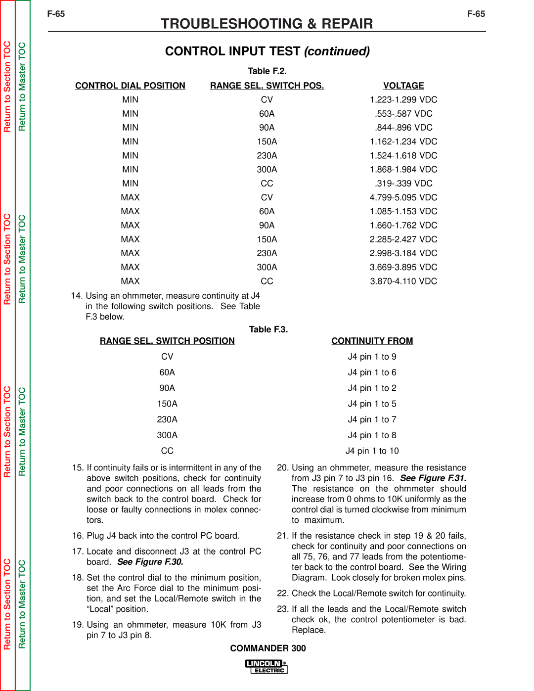
| Table F.2. |
|
| CONTROL DIAL POSITION | RANGE SEL. SWITCH POS. | VOLTAGE |
| MIN | CV | |
| MIN | 60A | |
| MIN | 90A | |
| MIN | 150A | |
| MIN | 230A | |
| MIN | 300A | |
| MIN | CC | |
| MAX | CV | |
| MAX | 60A | |
| MAX | 90A | |
| MAX | 150A | |
| MAX | 230A | |
| MAX | 300A | |
| MAX | CC | |
14.Using an ohmmeter, measure continuity at J4 in the following switch positions. See Table F.3 below.
| Table F.3. |
RANGE SEL. SWITCH POSITION | CONTINUITY FROM |
CV | J4 pin 1 to 9 |
60A | J4 pin 1 to 6 |
90A | J4 pin 1 to 2 |
150A | J4 pin 1 to 5 |
230A | J4 pin 1 to 7 |
300A | J4 pin 1 to 8 |
CC | J4 pin 1 to 10 |
Return to Section TOC
Return to Master TOC
15.If continuity fails or is intermittent in any of the above switch positions, check for continuity and poor connections on all leads from the switch back to the control board. Check for loose or faulty connections in molex connec- tors.
16.Plug J4 back into the control PC board.
17.Locate and disconnect J3 at the control PC board. See Figure F.30.
18.Set the control dial to the minimum position, set the Arc Force dial to the minimum posi- tion, and set the Local/Remote switch in the “Local” position.
19.Using an ohmmeter, measure 10K from J3 pin 7 to J3 pin 8.
20.Using an ohmmeter, measure the resistance from J3 pin 7 to J3 pin 16. See Figure F.31. The resistance on the ohmmeter should increase from 0 ohms to 10K uniformly as the control dial is turned clockwise from minimum to maximum.
21.If the resistance check in step 19 & 20 fails, check for continuity and poor connections on all 75, 76, and 77 leads from the potentiome- ter back to the control board. See the Wiring Diagram. Look closely for broken molex pins.
22.Check the Local/Remote switch for continuity.
23.If all the leads and the Local/Remote switch check ok, the control potentiometer is bad. Replace.