Manuals
/
Lucent Technologies
/
Cell Phone
/
Carrying Case
Lucent Technologies
3100, 3000
manual
User Group information screen
Models:
3100
3000
1
83
144
144
Download
144 pages
3.44 Kb
80
81
82
83
84
85
86
87
Page 83
Image 83
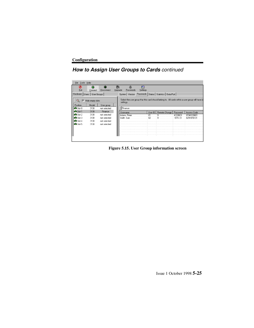
Configuration
How to Assign User Groups to Cards
continued
Figure 5.15. User Group information screen
Issue 1 October 1998
5-25
Page 82
Page 84
Page 83
Image 83
Page 82
Page 84
Contents
Definity Extender
Your Responsibility for Your System’s Security
Trademarks
Ordering Information
Contents
Specifications
Installing Switch Cards
Troubleshooting
Page
Important Safety Instructions
Outside the USA
Support Telephone Number
Customer Support Information
USA only
Security Your System Preventing Toll Fraud
Security Your System Preventing Toll Fraud
FCC Regulations
FCC Regulations
Equipment Attachment Limitations
Limited Warranty
Software End User License Agreement
Disclaimer of Warranty
Limitation of Liability
About This Manual
Intended Audience
Terms and Conventions
Example Purpose
Conventions used in this Manual
Description
How to Use This Manual
Chapter Number Title
Chapter Title Number
This page intentionally left blank
Product Overview
Chapter Contents Subject
Summary
Product Overview
Product
Remote Module Model
Switch Card Model
Product Overview Description
Typical Installation
What a typical installation looks like
Data
Configuration
Definity Extender Model 3000 Rack Description
Definity Extender Model 3100 Card Description
Switch Management Interface
8Issue 1 October
Specifications
Transmission
Specifications
Reference Information
Definity â Extender Model 3000 Rack Specifications
Specification
Rack Specifications
User Data Port
Definity â Extender Model 3100 Card Specifications
Analog Switch Card Specifications
Communication
Rack Installation
Considerations
Rack Installation
Lucent Supplied Equipment
Operational
Minimum PC Requirements
Customer Supplied Equipment
How to prepare the site for installation
Page
Rack Backplane
Rack Backplane connectors
Pstn
Backplane connectors defined
Rack Mounting
How to secure the Rack to a chassis
How to wire the Rack to the Pstn and Definity ECS
Twisted Pair Rack Termination
Connector P106
Connector P108
Connector P105
Wire Card Tip Ring Connector P107 Issue 1 October 1998
Data Port connectors on the Rack Backplane
How to connect the Cards to the Data Network
Feet
Remote PC
Terminology
RS-232 Cable Pinouts
Introduction
Before you Power Up the Rack
Power Up
18Issue 1 October
Installing Switch Cards
Information
Installing Switch Cards
Procedure
How to Install Switch Cards in the Rack
Settings
This page intentionally left blank
Configuration
System
Administrator
To set up the Rack
Password
Configuration Steps
How to Configure the Remote Module
Configuration Steps
How to connect to the Admin Port
Click Start Run
How to install the Switch Management Interface
Welcome screen
How to install the Switch Management Interface
Startup screen
How to Start the Switch Management Interface
QSelect from three options
Password File Options
Status Please wait while detecting hardware……………
How to Open a User Password File
Opening or creating a password file
How to Create a User Password File
Initial card detection screen
Initial Card Detection
Administrator password screen
Guidelines
How to Change the Administrator Password
How
Works
Change administrator password
Remote
User Access Code Overview
User
User ID
11. Access codes
Access Code
‘ Delete User ’ to clear entry
How to Add/Remove Users
Click ‘ + Add User’
12. User group list
How to Create/Delete User Groups
13. Assign a user group name
14. Add/Remove users from user groups
How to Add/Remove Users from User Groups
Available commands
QSetup tips
How to Assign User Groups to Cards
15. User Group information screen
16. Select hardware
How to Upload Passwords to Cards
17. Card selection
Parity Stopbits
How to set the Switch Card Data Port
Databits
18. Data port settings
19. Settings Icon
How to Access the Rack through Terminal Emulation
QSetting Passwords
Display a Password
How to disable passwords
Setting Parity
36Issue 1 October
Troubleshooting
Problems
Troubleshooting
Using built-in
Diagnostics
Baseline Checklist
How to Identify Problems
Chapter
Step Use the… For more information
Red
Blink See page…..in this Chapter
Green Yellow Meaning
Action
Meaning Green
Meaning Action Green
8Issue 1 October
Flags
Status Menu Information
Overview
Status
Status definitions
OK none Error
Action Required
Never connected
True
OK none
False
Flag definitions
OffqHook
Function
How a Remote User Flags a bad Switch Card
Flag reset options
Button
Statistics Menu Information
Update Now button Reset Stats button
10. Error Codes 104A to 110C
Error Codes
Error Codes
Description
11. Error Codes 111A to 124C
12. Error Codes 125B to 138B
Symptom Gaps in conversation or audio sounds choppy
How to Troubleshoot Audio Problems
How to Troubleshoot Audio Problems
QHow to Troubleshoot Audio Problems
13. Connect Error /No dialtone
How to Troubleshoot Connection Problems
Symptom Remote Module cannot connect to Switch Card
Error Message on Remote Phone Possible Cause Action
14. Connect Error/No Carrier
Error Message On Remote Phone
15. Connect Error/V42 Connect Error
16. Connect Error/ Password Not Verified
How to Troubleshoot Connection Problems
17. Unexpected Disconnect/Lost Carrier
18. Unexpected Disconnect/Lost V42, Lost Signal
How to Troubleshoot Connection Problems
Symptom Cannot connect PC or terminal to data network
How to Troubleshoot Data Connection Problems
How to Troubleshoot Data Connection Problems
Symptom Not satisfied with data performance Action
Select Configure System Select Passwords
How to reset a forgotten Administrator Password
This page intentionally left blank
Software Upgrades
Software Upgrading
How to check the software revisions of cards
Select target image
How to Upgrade Switch Card Software
Select hardware
Card selection
Click Finish
Ready to upgrade
Setup
How to Upgrade Software Using a Terminal program
Please wait while flash memory is being checked…
Verify Upgrade
Upgrading the Remote Module
Starting, REM Upgrade Erasing Flash at REM Completed
Upgrade Successful
Software Upgrading Verifying The Switch Upgrade
This page intentionally left blank
Glossary
Glossary
Glossary
LED
Switch Module
Top
Page
Image
Contents