MP-8 MP-9 Projectors
Typographical Conventions
Table of Contents
Page
Introduction
Projector
Functional Description
Madrigal Imaging Service Location
Purchaser’s Record and Servicing
Installation & Setup
Installation Considerations
Adjust the Display
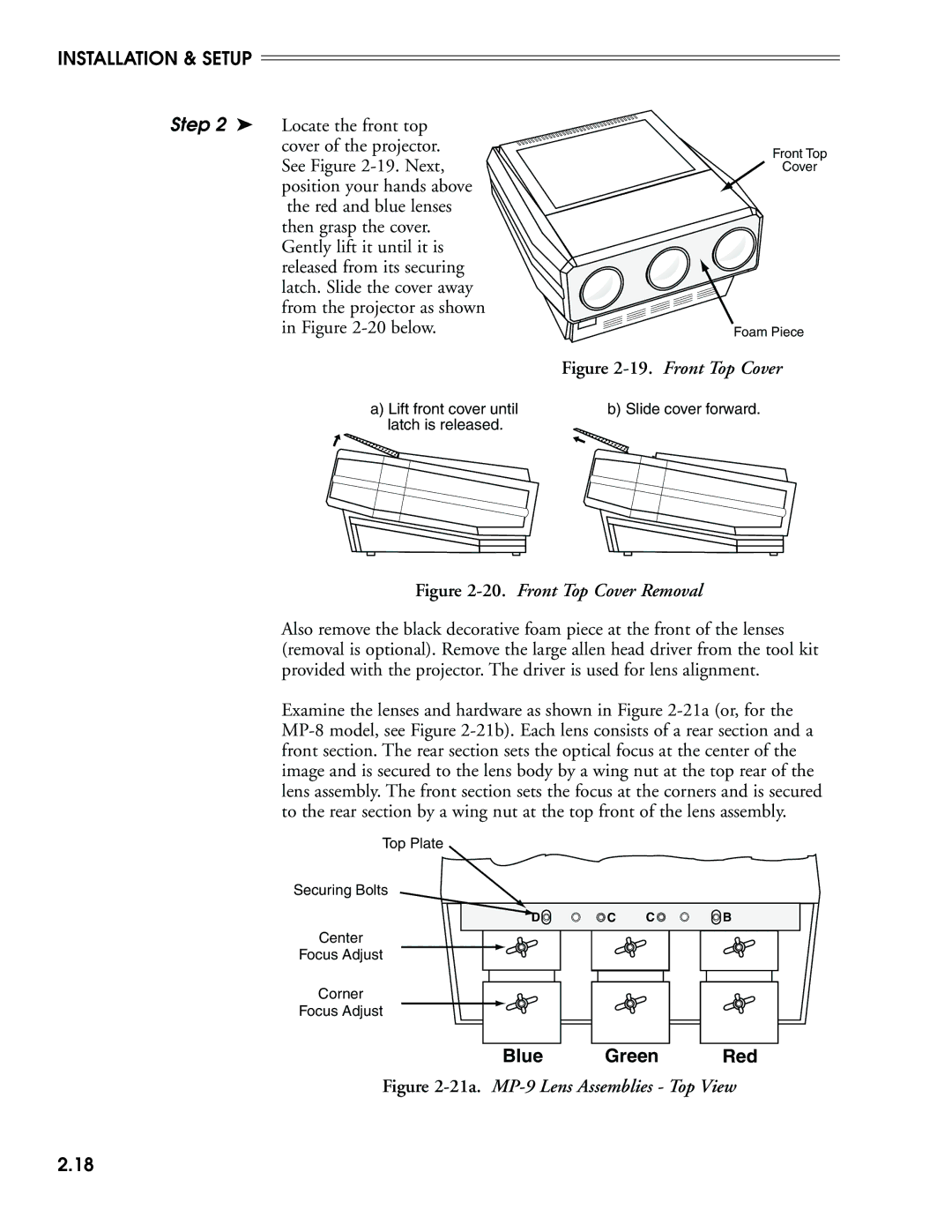
Step
Select the Input
Rear Screen, Ceiling Mount Installation
Front Screen Installations
Rear Screen Installations
Audience Coverage with Curved Screen
Screen Size
Throw Distance
Specified by diagonal size
Tune display size
Poor Screen Placement
Other
Considerations
Design of your projection system
Setup
Hardware
Keypad
Conversion
Battery Compartment
Keypad Operating Settings
JP1
All keystroke settings
Brite Tint Detail 2 . If pressed accidentally, press
Mounting
Floor Mount
Ceiling Mount
Rear Screen
Optical Rear Screen Systems
13.Diffused Rear Screen Installation
Diffused Rear Screen Systems
Power Connection
Source Connections
Serial Port Connections
17.Built-in RGB Interface Connections
Optical Alignment
Blue Green Red
Blue Green
22b. MP-8 Lens Assemblies Front View
Step
On the MP-9, tighten the three bolts labeled B
On the MP-9, locate the two
Keep the center defocused
Lens mounting plate. Turn
To display the next
Center horizontal line is perpendicular to the vertical
BeforeAfter
About Setup Memories
Memory
Must be repeated
About ASI and ASR
Setup Step
ASR Example #1
23.ASR System Example #1
ASR Example #2
24.ASR System Example #2
Acon Setup
29.ACON Installation Examples
Installation and Setup
Operation
Overview
Projector Basics
Wired Remote Keypad
Built-in Keypad
IR Remote Keypad
Full Function Keypad
Key Press Rules
Slidebars
Menus
Dialog Boxes
Message Boxes
Help Pages
Test Patterns
Context Sensitive Help
Guided Source Setup
Guided Mechanical Setup
Using Help
Guided Help
Rear Panel LEDs
Audio Mute Functions
System Status
Pages
Source Selection
Input
Selection
Example
Rear view
Direct Channel
Preferences entry in Section
Up/Down Channel
Source
Message
Setup Memories
Operation
Display Adjustments
Memory Allocation Locking Setup Memories
Primary Display Brightness Adjustments
Contrast
Detail
Color
Tint
Picture Functions
Position
Size
White Balance
Focus
Sync Fast/Slow
Blanking Top/Bottom/Left/Right
Auto Clamp On/Off
Retrace Short/Long
Decoder Options
Video Standard
Signal Routing
About the Sync Routing System
Geometry Functions
Keystone
Side Pin
Top
Bottom
Bow
Linearity
Skew
Convergence Registration
Convergence registration
Guided
Convergence
Interpolated
Random Access
Acon Automatic Convergence
Automatic Convergence Full, Touchup, and Center Only
Error Messages
Interrupting Acon
Learn Screen Auto, Manual
Item 2, Channel List, allows you to program the Channel List
Source Setup
Copy Setup
ASI with Save
Current Setup Locked/Unlocked
ASR On/Off
Message to indicate the action taken. If an Input
When to use the ASR feature
An Installation using the ASR Feature
Clear Current Setup
Select Internal Frequency
Be cleared by pressing
Name Field
Input Field
Recall Memory Field
Up/Down Field U/D
Input Memories
Auto Power-up On/Off
Preferences
Screen Messages On/Off
Blanking Time Auto, 0.5s to 5.0s
Programmable Events On/Off
Keypad Options
IR Sensor
Communication Setup
Remote Jack
Projector
Clock/Events
Baud Rate
Set Clock
Time
Programmable Events
Type Field
Type Field Events
Enabled Field
Interval Field
Start Field
General Notes about Programmable Events
About Channel Up/Down Events
Multi-projector Functions
Projector
Page
Maintenance
Guidelines
Labels Markings Projector Location
Power Cord
Attachments
Ventilation Slots
Servicing
Cleaning
Lens Cleaning Case Cleaning Acon Cleaning
Projector Response Problems
Symptom Cause/Remedy
Brightness to their proper settings
Contact your dealer or Madrigal for assistance
Symptom Projector does not respond to the Stby or Mute keys
You may not be holding down the key long enough to initiate
One second
Symptom
Symptom Display is very faint
Contrast or brightness settings may be set too low
Projection room may be too bright. Lower the intensity
Maintenance
Color and tint settings may require adjustment
Symptom Display is not rectangular in shape
Geometry settings. Press Geom for the Geometry menu
Message. If a Is displayed, unlock the setup. Press Util 1
Acon Errors
Page
Specifications
Specifications
Vertical Deflection
Horizontal Deflection
Power
High Voltage
Requirements
Inputs
Weight
Accessories
Environment Maximum Operating Range
Storage
Projector Dimensions
Physical
Page
Glossary
Color Temperature
Autolock
Bandwidth
Blanking Time
Current Setup
Memory
Gain or Screen
Gain
Gamma
Correction
Geometry
Help
Locator Assembly
Learn Screen
Line of Best
Viewing
Operation Level
Optical Screen
PAL Video
Pincushion
Setup Memory
Projector Retrace Time
Rise Time
RGB Video
Glossary
Glossary
Page
Menu Tree
Menu Tree
ASR/ASI Logic Diagrams
Match Input memory No match Memory
ASR/ASI Logic Diagrams
Communication Cables
RS-232 Serial Communications
Page
Keypad Reference
Page
Throw Distance Tables
Table F-1Throw Distance for MP-8 inches
Table F-1Throw Distance for MP-8 cm
Table F-1Throw Distance for MP-9 inches
Table F-1Throw Distance for MP-9 cm
Lenses
Throw Throw Distance Distance Formula Formula Screen Screen
Page
Index
INDEX.2
DAY Limited Warranty