3)Select the OC icon, and click on the selected outdoor unit.
Select the icon of the outdoor unit connected to the watt hour meter by clicking on the icon. Then, click in the cell of the selected outdoor unit. The outdoor unit is now connected to the watt hour meter.
4)Repeat steps 1) to 3).
Repeat this procedure on each of the outdoor units connected to a watt hour meter. Also, set the options for every watt hour meter that has an outdoor unit connected to it.
5)Select [OK] button.
When done with these settings, click the [OK] button.
*If the [Cancel] button is clicked, the settings are interrupted and the screen returns to the initial window.
Delete Watt Hour Meter Relationships.
Follow these steps to delete the relationship between an outdoor unit and a watt hour meter.
[Procedure]
1)Click on the icon to be deleted.
Click on the icon of the outdoor unit to be deleted.
The relationship between that unit and the watt hour meter is deleted.
Note:
•If a unit has not been assigned to a watt hour meter, a warning is displayed. Correct the setting to proceed.
•This setting window is not displayed for Without WHM connection proportionally divided electric charge (manual input of the electric amount).
Select
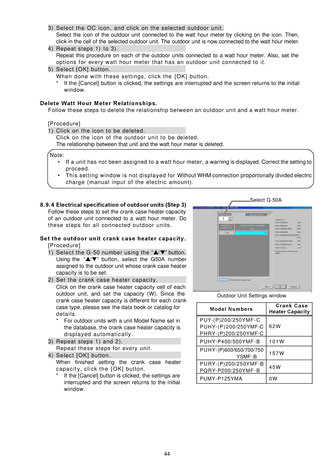
8.9. 4 Electrical specification of outdoor units (Step 3) Follow these steps to set the crank case heater capacity of an outdoor unit connected to a watt hour meter. Do these steps for all connected outdoor units.
Set the outdoor unit crank case heater capacity. [Procedure]
1)Select the ![]() /
/ ![]() ” button. Using the “
” button. Using the “![]() /
/![]() ” button, select the
” button, select the
2)Set the crank case heater capacity.
Click on the crank case heater capacity cell of each
outdoor unit, and set the capacity (W). Since the |
| Outdoor Unit Settings window |
| |||
crank case heater capacity is different for each crank |
|
| ||||
|
|
|
| |||
|
|
|
| |||
case type, please see the data book or catalog for | Model Numbers | Crank Case | ||||
details. | Heater Capacity | |||||
| ||||||
|
|
| ||||
* For outdoor units with a unit Model Name set in | 6 2 W | |||||
the database, the crank case heater capacity is | ||||||
displayed automatically. |
|
| ||||
|
|
|
|
|
| |
3) Repeat steps 1) and 2). |
|
| 1 0 1 W | |||
Repeat these steps for every unit. |
|
|
| |||
1 5 7 W | ||||||
4) Select [OK] button. |
|
| YSMF | |||
|
|
|
| |||
When finished setting the crank case heater |
|
|
| |||
4 5 W | ||||||
capacity, click the [OK] button. | ||||||
* If the [Cancel] button is clicked, the settings are |
|
| ||||
0 W | ||||||
interrupted and the screen returns to the initial | ||||||
|
|
| ||||
|
|
| ||||
window. |
|
|
| |||
44
