3.System Configuration
3.1System Configuration Example
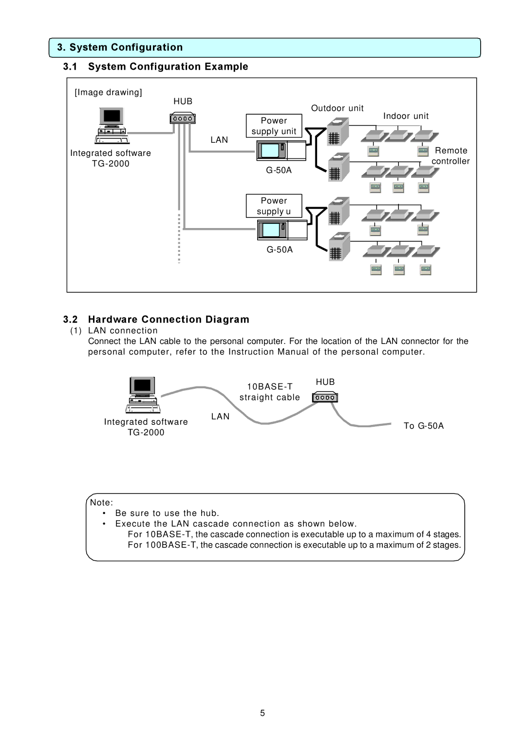
[Image drawing] | HUB |
| |
| Outdoor unit | ||
|
| ||
| Power | Indoor unit | |
|
| ||
| supply unit |
| |
| LAN |
| |
Integrated software |
| Remote | |
| controller | ||
| |||
|
| ||
| Power |
| |
| supply u |
| |
|
|
3.2Hardware Connection Diagram
(1)LAN connection
Connect the LAN cable to the personal computer. For the location of the LAN connector for the personal computer, refer to the Instruction Manual of the personal computer.
|
|
|
| LAN |
| |
Integrated software | To | |||||
|
| |||||
|
|
| ||||
|
|
|
| |||
|
|
|
|
|
| |
Note:
•Be sure to use the hub.
•Execute the LAN cascade connection as shown below.
For
5