[JAM error]
2-1 Paper input jam (1st tray)
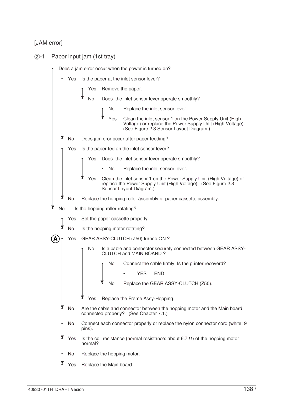
•Does a jam error occur when the power is turned on?
• Yes Is the paper at the inlet sensor lever?
▼
• No
• Yes
• | Yes | Remove the paper. | ||
▼ | No | Does the inlet sensor lever operate smoothly? | ||
• | ||||
|
| • | No | Replace the inlet sensor lever |
|
| ▼ | Yes | Clean the inlet sensor 1 on the Power Supply Unit (High |
|
| • | ||
Voltage) or replace the Power Supply Unit (High Voltage). (See Figure 2.3 Sensor Layout Diagram.)
Does jam eror occur after paper feeding?
Is the paper fed on the inlet sensor lever?
• Yes Does the inlet sensor lever operate smoothly?
▼
•
▼
• No
• No | Replace the inlet sensor lever. |
▼
• Yes Clean the inlet sensor 1 on the Power Supply Unit (High Voltage) or replace the Power Supply Unit (High Voltage). (See Figure 2.3 Sensor Layout Diagram.)
No Replace the hopping roller assembly or paper cassette assembly.
Is the hopping roller rotating?
• | Yes | Set the paper cassette properly. | |||||
▼ | No | Is the hopping motor rotating? | |||||
• | |||||||
A • | Yes | GEAR | |||||
|
| • | No | Is a cable and connector securely connected between GEAR ASSY- | |||
|
|
|
| CLUTCH and MAIN BOARD ? | |||
|
|
|
| • | No | Connect the cable firmly. Is the printer recoverd? | |
|
|
|
|
|
| • | YES END |
|
|
|
| ▼ | No | Replace the GEAR | |
|
|
|
| • | |||
|
| ▼ | Yes | Replace the Frame | |||
|
| • | |||||
▼
• No Are the cable and connector between the hopping motor and the Main board connected properly? (See Chapter 7.1.)
• No Connect each connector properly or replace the nylon connector cord (white: 9 pins).
▼
• Yes
• No
▼
• Yes
Is the coil resistance (normal resistance: about 6.7 Ω) of the hopping motor normal?
Replace the hopping motor.
Replace the Main board.
40930701TH DRAFT Vesion | 138 / |
