Appendix B RS-232C SERIAL INTERFACE
1) Connector
• | Printer side | : | |
|
|
| Type |
• | Cable side | : | |
|
|
| Type |
Note: Plug shall be able to be fixed with a lock screw.
2)Cable
• Cable length: 6 ft (1.8m) max. (Cable shall be shielded)
Note: Cable is not provided.
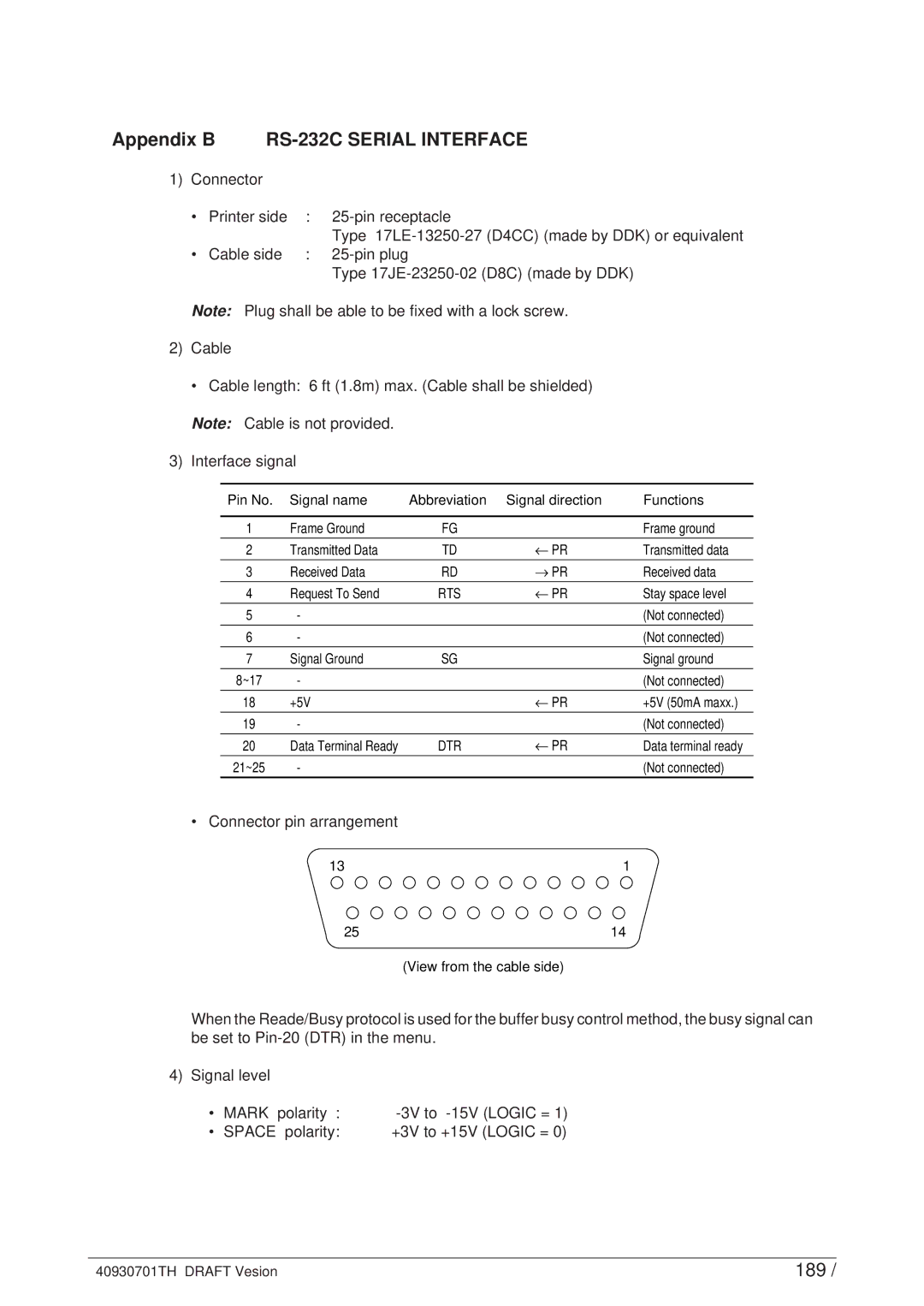
3) Interface signal
Pin No. | Signal name | Abbreviation | Signal direction | Functions |
|
|
|
|
|
1 | Frame Ground | FG |
| Frame ground |
2 | Transmitted Data | TD | ← PR | Transmitted data |
3 | Received Data | RD | → PR | Received data |
|
|
|
|
|
4 | Request To Send | RTS | ← PR | Stay space level |
5 | - |
|
| (Not connected) |
6 | - |
|
| (Not connected) |
|
|
|
|
|
7 | Signal Ground | SG |
| Signal ground |
8~17 | - |
|
| (Not connected) |
18 | +5V |
| ← PR | +5V (50mA maxx.) |
|
|
|
|
|
19 | - |
|
| (Not connected) |
20 | Data Terminal Ready | DTR | ← PR | Data terminal ready |
21~25 | - |
|
| (Not connected) |
• Connector pin arrangement
13 | 1 |
25 | 14 |
| (View from the cable side) |
When the Reade/Busy protocol is used for the buffer busy control method, the busy signal can be set to
4) Signal level
• | MARK polarity : | ||
• | SPACE polarity: | +3V to | +15V (LOGIC = 0) |
40930701TH DRAFT Vesion | 189 / |