Manuals
/
Oki
/
Computer Equipment
/
Printer
Oki
24DX
manual
164
Models:
24DX
1
145
218
218
Download
218 pages
60.49 Kb
142
143
144
145
146
147
148
149
Troubleshooting
Specs
Parts list
Interconnect Signal Diagram
ERROR74
One side wire-bonding head
System Configuration
Connector IMSA-9714N-14A
Check at the time of assembly
Tray auto Setting switch
Page 145
Image 145
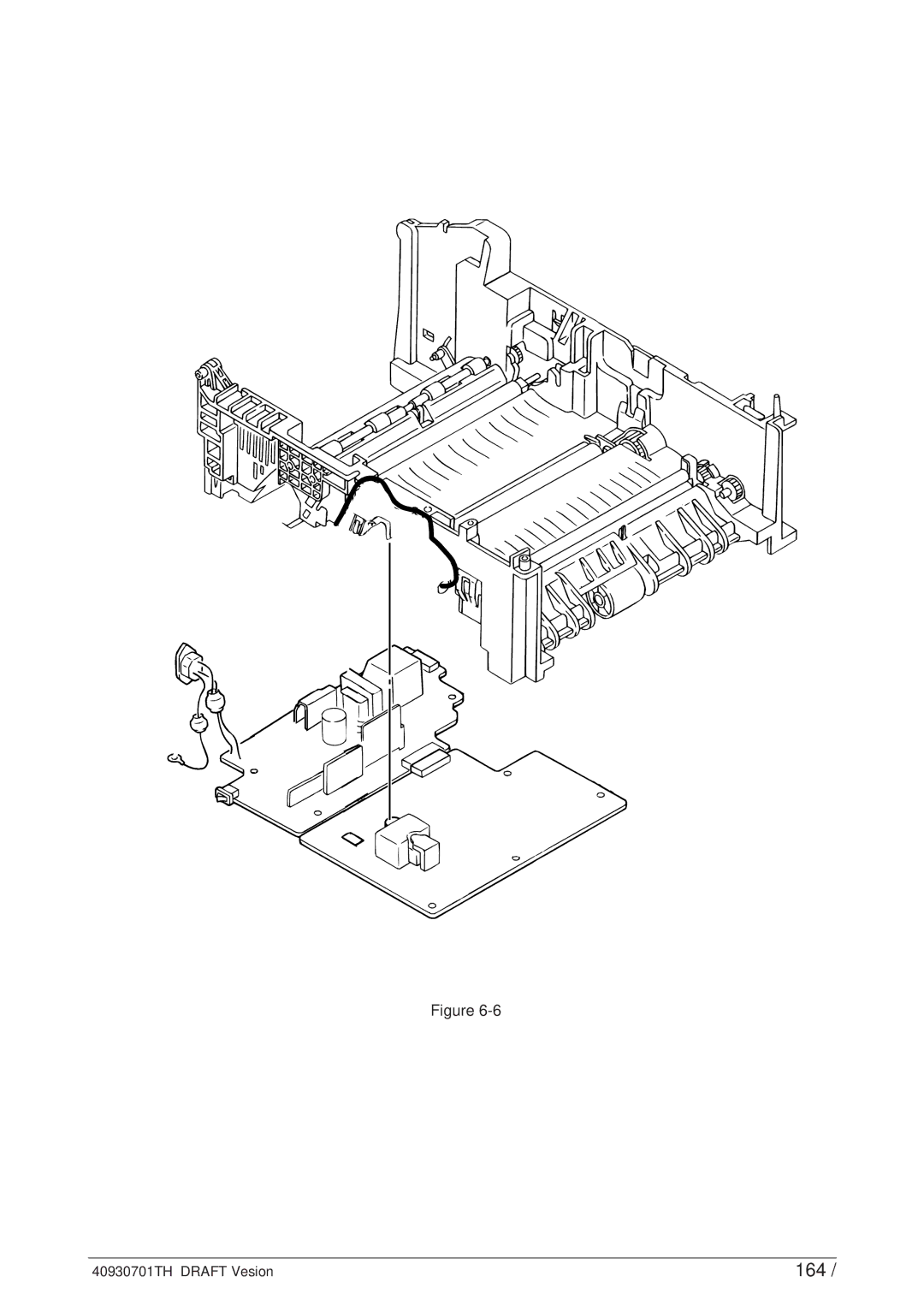
Figure
6-6
40930701TH DRAFT Vesion
164 /
Page 144
Page 146
Page 145
Image 145
Page 144
Page 146
Contents
Draft Version
LED Page Printer
Preface
Contents
Lever-Paper end & Lever-Paper near end
Connector IMSA-9714N-14A
101
105
191
Interconnection Diagram 213 PCB Layout 214
Functions 191 Appearance and Parts Name
192
Parts List
OKI HSP
System Configuration
Shows the printer unit configuration
Printer Configuration
Optional Configuration
40930701TH Draft Vesion
Specification
Temperature and humidity
Safety Standards
Shows an OKIPAGE24DX / OKIPAGE24dx block diagram
OKIPAGE24DX / OKIPAGE24dx block diagram
Program/font ROMs
Main Control Board BOARD-FFF
PCL ROM
PS ROM
Menu
Eeprom
LAN
ON/X-OFF Rbst X-ON
Board-FSL or Board-FSL-2 4MB 8MB
Power Supply Unit
OFF
Shows the sensor layout diagram
LED Head
Electro-photographic Process
40930701TH Draft Vesion
40930701TH Draft Vesion
Paper Eject roller
PWM1-P Cluch for hopping PWM2-P Cluch for Registration
DMON-N Drum Motor HMON-N Hopping Motor
Duplex Unit
Printer Stacker Duplex Printing Timing Chart
DUPRSNS-N Rear Sensor inDUPLEX Unit DUPFSNS-N Front Sensor
Duplex Unit OFF Paper Tray Printer
Hopping Motor Front Feeder Duplex Unit 1st Tray
Pressure Roller Regist Roller
Start printing. after the paper turns off the Write Sensor
~30
Home position
Front Hopping Shaft
180 FF Cam Micro SW Front Feeder Plate
Gear E Clutch Feed Gear D Align Roller Main Motor
Power Supply
40930701TH Draft Vesion
Image drum Paper Transfer roller
Heater Separation Claw
Image Drum Cleaning Roller Power Supply Transfer Roller
Roller
SNS DUP
Retracting paper Sending out paper
LSI Eeprom
STRB4-N STRB3-N Data
Clock
LED LED LED LED LED LED LED
Data
Read
Clock Load
STRB1-N STRB2-N STRB3-N STRB4-N
STRB4~1
Direct
CPU
One side wire-bonding head
Correction
Total 5200 clocks
LED Correction Data
Clock Load DATA3~0 STRB1-N STRB2-N STRB3-N STRB4-N
Printing operation timing chart is shown below
Paper Jam Detection
Cover Open
Stirring Gear
Toner Low Detection
Toner LOW state
Toner Full state
T1 2.727/4 727 SEC
Size Detection
Stacker-full Detection
Paper size
SW1 SW2 SW3 SW4
Precautions for Parts Replacement
Service Tools Place of use
Parts Layout
Roller
Guide
Photo sensor Motor Solenoid Assy
This section explains how to below
How to Change Parts
40930701TH Draft Vesion
Unlock this part before removing 40930701TH Draft Vesion
40930701TH Draft Vesion
40930701TH Draft Vesion
40930701TH Draft Vesion
40930701TH Draft Vesion
40930701TH Draft Vesion
40930701TH Draft Vesion
40930701TH Draft Vesion
40930701TH Draft Vesion
40930701TH Draft Vesion
40930701TH Draft Vesion
View a
40930701TH Draft Vesion
40930701TH Draft Vesion
40930701TH Draft Vesion
40930701TH Draft Vesion
40930701TH Draft Vesion
40930701TH Draft Vesion
40930701TH Draft Vesion
40930701TH Draft Vesion
40930701TH Draft Vesion
40930701TH Draft Vesion
40930701TH Draft Vesion
40930701TH Draft Vesion
40930701TH Draft Vesion
40930701TH Draft Vesion
40930701TH Draft Vesion
40930701TH Draft Vesion
40930701TH Draft Vesion
40930701TH Draft Vesion
40930701TH Draft Vesion
40930701TH Draft Vesion
Pull the Duplex Unit out of the unit
Printer Groove
PLATE-Earth F/R 40930701TH Draft Vesion
40930701TH Draft Vesion
From the results of installation
View
40930701TH Draft Vesion
Periodic Replacing Part
Cleaning
118
119
Points to Check before Correcting Image Problems
Troubleshooting Tips
Tips for Correcting Image Problems
120
Troubleshooting Flow
Preparation for Troubleshooting
121
Category LCD status message Trouble or status Remedy
122
DUPLEX, Simplex
Received and abandoned until the completion of a job
123
124
Manual A4 Size Request
125
Load the requested paper in tray
126
FFF
127
DUP Insns on
128
DUP Insns OFF
DUP R SNS on ~ DUP F SNS on
129
If the error occurs frequently, see chapter
Category
130
LCD Ready
Trouble or status Remedy Message
Trouble or status Remedy
131
Category LCD
132
ERROR80
ERROR74
133
Time-out between the printer and the operator panel
134
Printer does not work normally after being turned on
YES END
Yes Is
135
Initializing
Message shown in the LCD display? Replace the Main board
136
Power Connector
INLETSW1
137
138
JAM error Paper input jam 1st tray
Replace the Gear ASSY-CLUTCH Z50
Paper input jam front feeder
Replace the front feeder paper sensor assembly
139
140
Paper feed jam
Go to on the next page a
141
142
143
Paper exit jam
144
Duplex Input JAM
Duplex Feed JAM
Duplex Feed JAM1
145
Is the Duplex Front sensor lever operating normally?
146
Sensor F/R
147
Paper size error
Does the outlet sensor lever operate smoothly
148
Fuser unit error Error 71, Error 72, Error
149
F time-out between printer and Duplex Unit Error
F time-out between printer and optional tray Error
150
151
Message cannot be received through the parallel interface
152
Message cannot be received through the serial interface
Data cannot be received through the OKI HSP interface
Synchronous serial I/O error Error
153
OK?
Abnormal images
154
Image are light or blurred a whole
Replace the Main board or Power Supply Unit High Voltage
155
Replace the image drum cartridge
Black paper is output
Dark background density
156
Enter keys. Set the LED head drive time. Refer to Section
157
Black belts or stripes in the vertical direction
Enter keys. Set the LED head drive time
Refer to Section
158
Cyclic error
159
Print voids
160
Poor fusing
161
White belts or streaks in the vertical direction
Yes Replace the LED head Has the trouble been removed?
Blockly faded print
Snowy print of high density pattern
162
163
164
165
Interconnect Signal Diagram
To Printer Unit
166
167
PCB Layout
Main board BOARD-FFF
Power supply board High voltage
Power supply board AC120V/230V
168
LEX-PCB
169
CPU
ROM
170
Resistance Check
171
172
Program/Font ROM Location
Case of EP ROM or OTP ROM
Case of Mask ROM
173
Printer Unit
174
SMCD6X280BDX10BL
175
Duplex Unit ODA
Frame-Main
176
Frame-Main Unit 1/2
177
Frame-Main Unit 2/2
178
Roller ASS.-BK
PLATE-FG F
Base Unit
179
Base Unit 1/2
180
GEAR-Z38 NK3-16SUS
GEAR-Z58
Base Unit 2/2
181
BRACKET-AC
182
Duplex Unit 1/2
183
GEAR-Z40S6
PULLEY-MXL25
Duplex Unit 2/2
184
SPRING-SL
NK2-12SUS
185
Connector pin arrangement
LOW
186
High
On-line → off-line switching timing by ON-LINE SW
Timing charts Compatible mode Data receiving timing
Off-line → on-line switching timing by ON-LINE SW
187
188
Nibble Mode Conforms to Ieee 1284 spec ECP Mode
INPUT. Prime Busy Select
189
Appendix B RS-232C Serial Interface
Input Output
190
Input
Appearance and Parts Name
Functions
191
192
Driving Mechanism
193
194
Hopper Mechanism
195
Precautions Concerning Parts Replacement
OKI P/N
196
4PP4076-5395P1
This section describes the layout of the main components
197
198
Parts Replacement Methods
199
200
201
202
203
204
205
206
207
208
209
Preparations for the Troubleshooting
Precautions Prior to the Troubleshooting
210
211
Troubleshooting Method
YES
212
Tray auto Setting switch
Interconnection Diagram 2nd tray/ 3rd
To Printer Unit 2nd Tray
To 3rd Tray
BBB-PCB
214
215
High Capacity Second/ Third Paper Feeder 1/2
216
High Capacity Second/ Third Paper Feeder 2/2
217
218
External View and Component Names
Main functions are the followings Paper that can be used
Approximately 50 sheets of envelopes can be set at a time
219
General Mechanism
220
221
222
223
224
Check at the time of assembly
225
226
227
228
229
230
231
232
Check Feeder
233
Checkfeeder
234
235
Interconnection Diagram
236
237 /237
Top
Page
Image
Contents