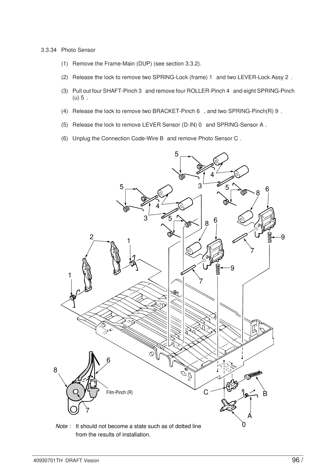
3.3.34Photo Sensor
(1)Remove the
(2)Release the lock to remove two
(3)Pull out four
(u) 5.
(4)Release the lock to remove two
(5)Release the lock to remove LEVER Sensor
(6)Unplug the Connection
|
| 5 |
|
|
|
| 4 |
| |
| 5 | 3 | 5 | 6 |
|
|
| 8 | |
|
| 4 |
|
|
| 3 | 5 | 6 |
|
|
| 8 |
| |
2 | 1 |
|
| 9 |
|
|
|
| |
|
|
| 7 |
|
|
|
| 9 |
|
1 |
| 7 |
|
|
|
|
|
| |
6
8
C | B | |
7 |
| A |
|
| |
Note : It should not become a state such as of dotted line |
| 0 |
from the results of installation.
40930701TH DRAFT Vesion | 96 / |