40930701TH DRAFT Vesion
Unit |
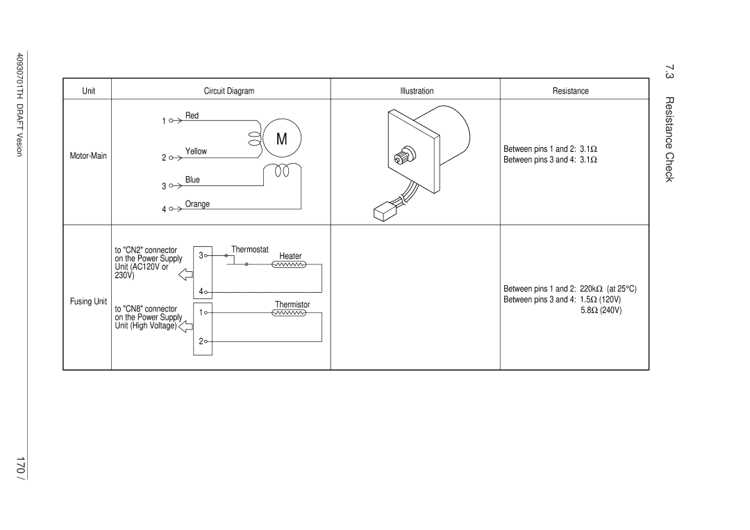
| Circuit Diagram | Illustration | Resistance |
| 1 | Red |
|
|
|
|
|
| |
|
| Yellow | M | Between pins 1 and 2: 3.1Ω |
2 |
| |||
|
| Ω | ||
|
|
|
| Between pins 3 and 4: 3.1 |
7.3 Resistance Check
3
4
Blue
Orange
170 /
to "CN2" connector on the Power Supply Unit (AC120V or 230V)
Fusing Unit
to "CN8" connector
on the Power Supply
Unit (High Voltage)
3
4
1
2
Thermostat
Heater
Thermistor
Between pins 1 and 2: 220kΩ (at 25°C)
Between pins 3 and 4: 1.5Ω (120V) 5.8Ω (240V)