2.2Power Supply Unit
The power supply unit consists of an AC filter circuit, a low voltage power supply circuit, a high voltage power supply circuit, heater drive circuit, and photosensors.
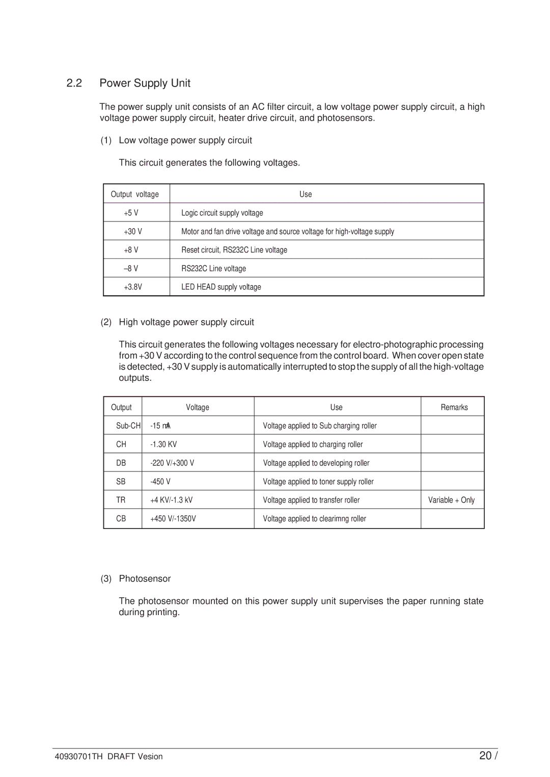
(1)Low voltage power supply circuit
This circuit generates the following voltages.
Output voltage | Use |
|
|
+5 V | Logic circuit supply voltage |
|
|
+30 V | Motor and fan drive voltage and source voltage for |
|
|
+8 V | Reset circuit, RS232C Line voltage |
|
|
RS232C Line voltage | |
|
|
+3.8V | LED HEAD supply voltage |
|
|
(2)High voltage power supply circuit
This circuit generates the following voltages necessary for
Output |
| Voltage | Use | Remarks |
|
|
|
| |
Voltage applied to Sub charging roller |
| |||
|
|
|
| |
CH | Voltage applied to charging roller |
| ||
|
|
|
|
|
DB | V/+300 V | Voltage applied to developing roller |
| |
|
|
|
|
|
SB | V | Voltage applied to toner supply roller |
| |
|
|
|
| |
TR | +4 | Voltage applied to transfer roller | Variable + Only | |
|
|
|
| |
CB | +450 | Voltage applied to clearimng roller |
| |
|
|
|
|
|
(3)Photosensor
The photosensor mounted on this power supply unit supervises the paper running state during printing.
40930701TH DRAFT Vesion | 20 / |