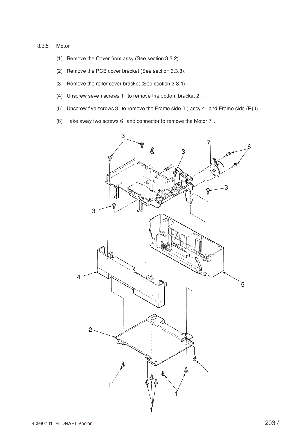
3.3.5Motor
(1)Remove the Cover front assy (See section 3.3.2).
(2)Remove the PCB cover bracket (See section 3.3.3).
(3)Remove the roller cover bracket (See section 3.3.4).
(4)Unscrew seven screws 1 to remove the bottom bracket 2.
(5)Unscrew five screws 3 to remove the Frame side (L) assy 4 and Frame side (R) 5.
(6)Take away two screws 6 and connector to remove the Motor 7.
3
7
3
6
![]() 3
3
3
4
5
2
1
1
1
1
40930701TH DRAFT Vesion | 203 / |