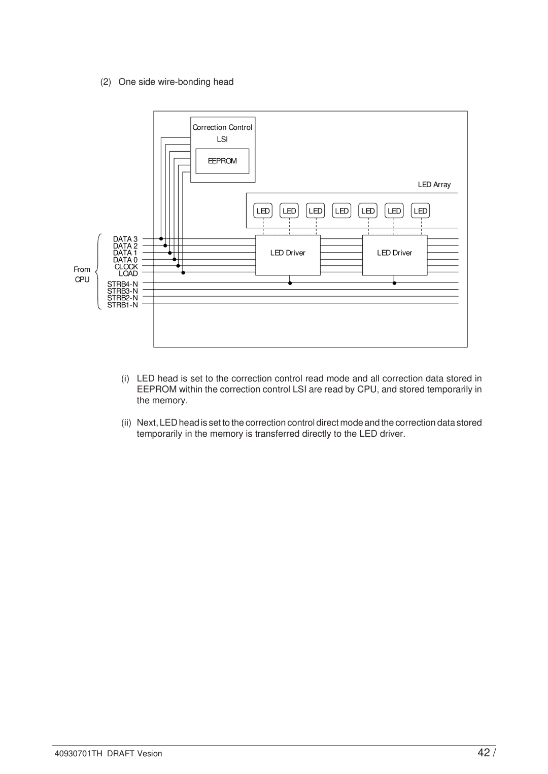
(2) One side wire-bonding head
From
CPU
DATA 3 DATA 2 DATA 1 DATA 0 CLOCK
LOAD
Correction Control
LSI
EEPROM
| LED Array |
LED LED LED | LED LED LED LED |
LED Driver | LED Driver |
(i)LED head is set to the correction control read mode and all correction data stored in EEPROM within the correction control LSI are read by CPU, and stored temporarily in the memory.
(ii)Next, LED head is set to the correction control direct mode and the correction data stored temporarily in the memory is transferred directly to the LED driver.
40930701TH DRAFT Vesion | 42 / |