Line Interface | Hardware Interface |
|
|
|
|
ce ll 5 3 B yte
|
| U N I | ||
| M SB | LSB | ||
Byte |
| G FC (4) | VPI(4) | |
| VPI(4) | VC I(4) | ||
er 5 |
|
|
|
|
| VC I(8) | |||
ad |
| VC I(4) | PT(3) | (1) |
he |
| |||
|
|
|
| |
|
| H EC (8) | ||
4 8 B yte |
|
|
|
|
| U ser Inform ation | |||
| ||||
p aylo ad |
| |||
|
|
|
| |
|
|
|
| |
|
| N N I |
|
|
| |||
| M SB | LSB |
|
|
| |||
|
| VPI(8) |
|
|
|
| ||
|
| VPI(4) | VC I(4) |
|
|
|
| |
|
|
|
|
|
|
|
|
|
C LP |
| VC I(8) |
| C LP | U N I: U | |||
| VC I(4) | PT(3) | (1) |
| ||||
|
|
|
| N N I: N etw | ||||
|
|
|
|
|
|
| ||
|
| H EC (8) |
|
|
|
| ||
|
|
|
|
|
|
| G FC : G eneric Flow C ontrol | |
|
| U ser Inform ation |
|
| VPI: | Virtual Path Identifier | ||
|
|
|
| VC I: | Virtual C hannel Identifier | |||
|
|
|
|
|
|
| PT: | Payload Type |
|
|
|
|
|
|
| C LP: C ell Loss Priority | |
|
|
|
|
|
|
| H EC : H eader Error C ontrol | |
G FC | VPI | VC I | PT | C LP | use | ||
0 | 0 | 0 | x | 0 | unassigned cell | ||
0 | x | 1 | 0,2 | * | m eta signalling (default VPI=0) | ||
0 | x | 2 | * | general broadcast signalling (default VPI=0) | |||
0 | x | 3 | 0,2 | * | segm ent O AM F4 | ||
0 | x | 4 | 0,2 | * | |||
0 | x | 5 | * | ||||
0 | x | 16 |
| * | ILM I (Interim Local M anagem ent Interface) | ||
|
|
| 0 | * | user data cell, no congestion, SD U | ||
|
|
| 1 | * | user data cell, congestion, SD U | ||
|
| any | 2 | * | user data cell, congestion, SD U | ||
0 | x | value | 3 | * | user data cell, no congestion, SD U | ||
other |
|
|
|
| |||
4 | * | segm ent O AM F5 | |||||
|
| than | |||||
|
| 5 | * | ||||
|
| 0 | |||||
|
|
| 6 | * | reserved for traffic cont. and resource m an. | ||
|
|
| 7 | * | reserved | ||
|
|
|
|
|
|
| |
0norm al priority 1 low er priority
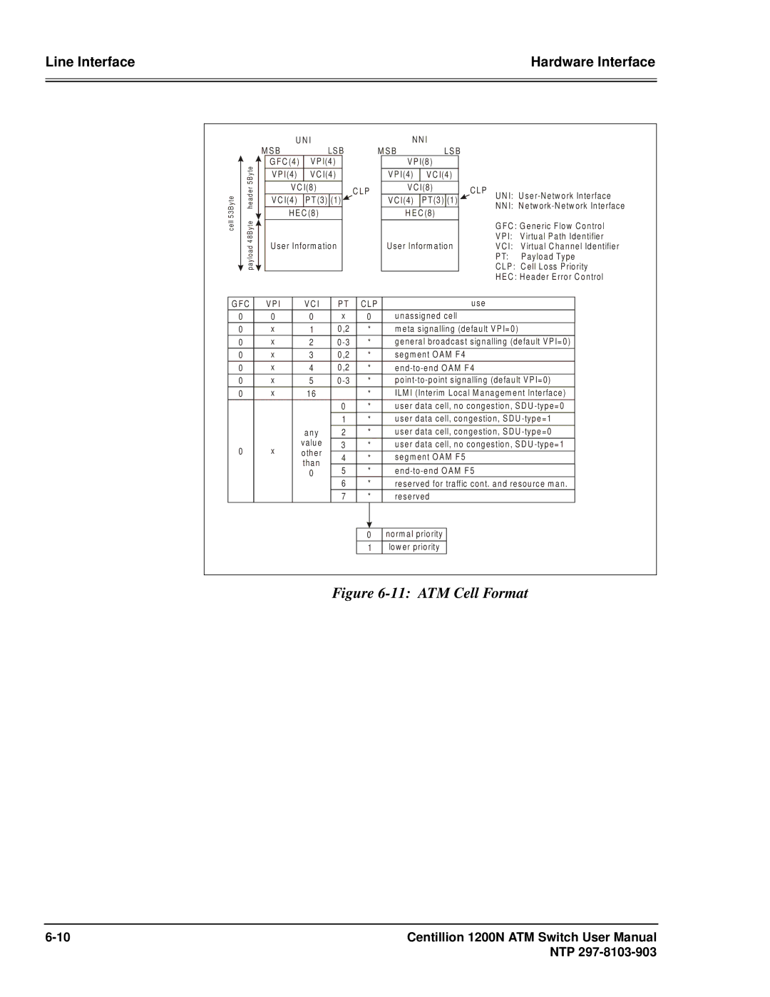
Figure 6-11: ATM Cell Format
Centillion 1200N ATM Switch User Manual | |
| NTP |