Chapter 4 - Hardware Description
The Net-2/Net-4/Net-8 ISDN/T1-CAS Network Interface Data Stream
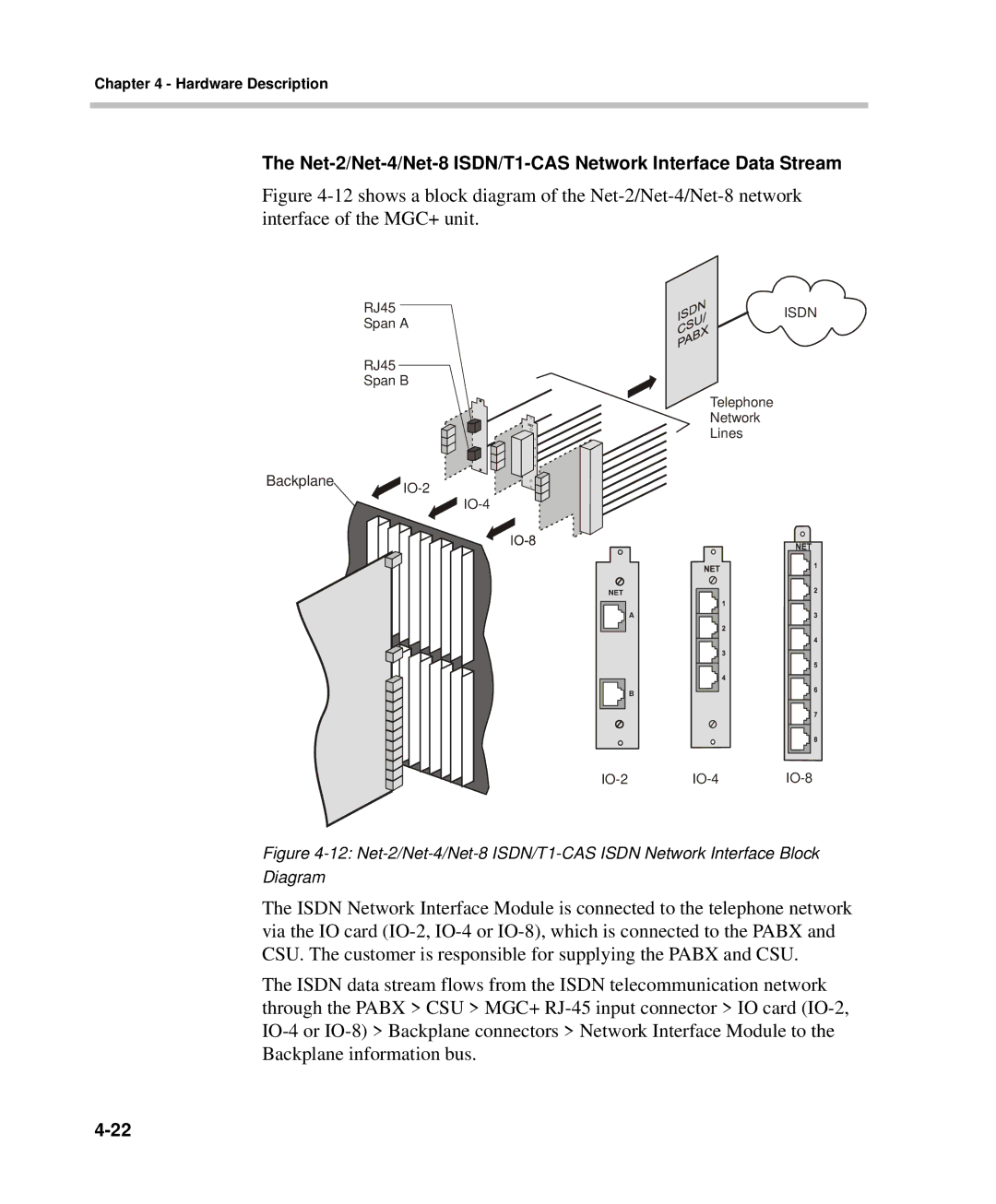
Figure 4-12 shows a block diagram of the Net-2/Net-4/Net-8 network interface of the MGC+ unit.
RJ45 | ISDN |
Span A |
|
RJ45
Span B
Telephone
Network
Lines
Backplane | |
| |
|
NET |
|
|
| A |
|
| B |
|
Figure 4-12: Net-2/Net-4/Net-8 ISDN/T1-CAS ISDN Network Interface Block Diagram
The ISDN Network Interface Module is connected to the telephone network via the IO card
The ISDN data stream flows from the ISDN telecommunication network through the PABX > CSU > MGC+