Chapter 3 - System Architecture
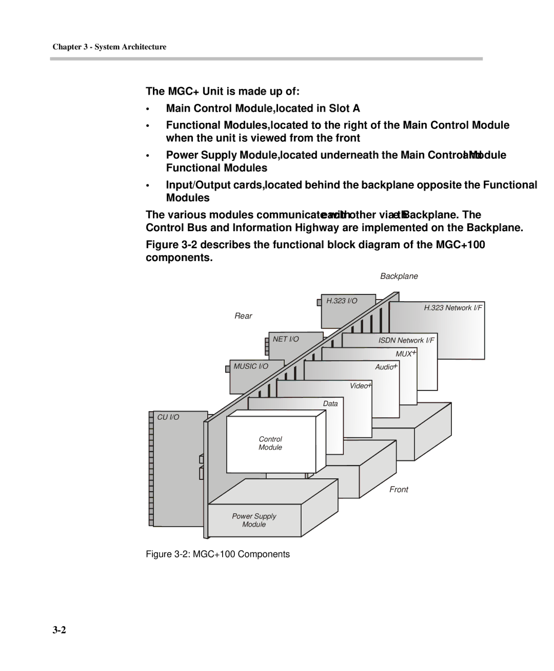
The MGC+ Unit is made up of:
•Main Control Module, located in Slot A
•Functional Modules, located to the right of the Main Control Module when the unit is viewed from the front
•Power Supply Module, located underneath the Main Control Module and Functional Modules
•Input/Output cards, located behind the backplane opposite the Functional Modules
The various modules communicate with each other via the Backplane. The Control Bus and Information Highway are implemented on the Backplane.
Figure 3-2 describes the functional block diagram of the MGC+100 components.
|
|
|
|
|
|
|
|
|
|
| Backplane | ||
|
|
|
|
|
|
|
|
|
| H.323 I/O |
|
| H.323 Network I/F |
|
|
|
|
|
|
|
|
|
|
|
| ||
|
|
|
| Rear |
|
|
|
| |||||
|
|
|
|
|
|
|
|
| |||||
|
|
|
|
|
| NET I/O |
|
| ISDN Network I/F | ||||
|
|
|
|
|
|
|
| ||||||
|
|
|
|
|
|
|
|
|
|
|
| MUX+ | |
|
|
|
|
|
|
|
|
|
|
|
| ||
|
|
|
|
|
|
|
|
|
|
|
| ||
|
|
|
|
|
|
|
|
|
|
|
| ||
|
|
|
| MUSIC I/O |
| Audio+ | |||||||
|
|
|
|
| |||||||||
|
|
|
|
|
|
|
|
|
| Video+ | |||
|
|
|
|
|
|
|
|
|
| Data | |||
CU I/O |
|
|
|
|
| ||||||||
|
|
|
| Control |
|
|
|
|
| ||||
|
|
|
|
|
|
|
|
| |||||
|
|
|
| Module |
|
|
|
|
| ||||
|
|
|
|
|
|
|
|
|
|
|
|
|
|
|
|
|
|
|
|
|
|
|
|
|
|
|
|
|
|
|
|
|
|
|
|
|
|
|
|
|
|
|
|
|
|
|
|
|
|
|
|
|
|
|
|
Front
Power Supply
Module