Chapter 4 - Hardware Description
Control Unit
The Main Control Unit performs the functions of conference setup, conference termination, and resource allocation in both the MGC+100 and the MGC+50. The Main Control Module has an
The front LED’s indicate the status if the module is in operation and functioning properly.
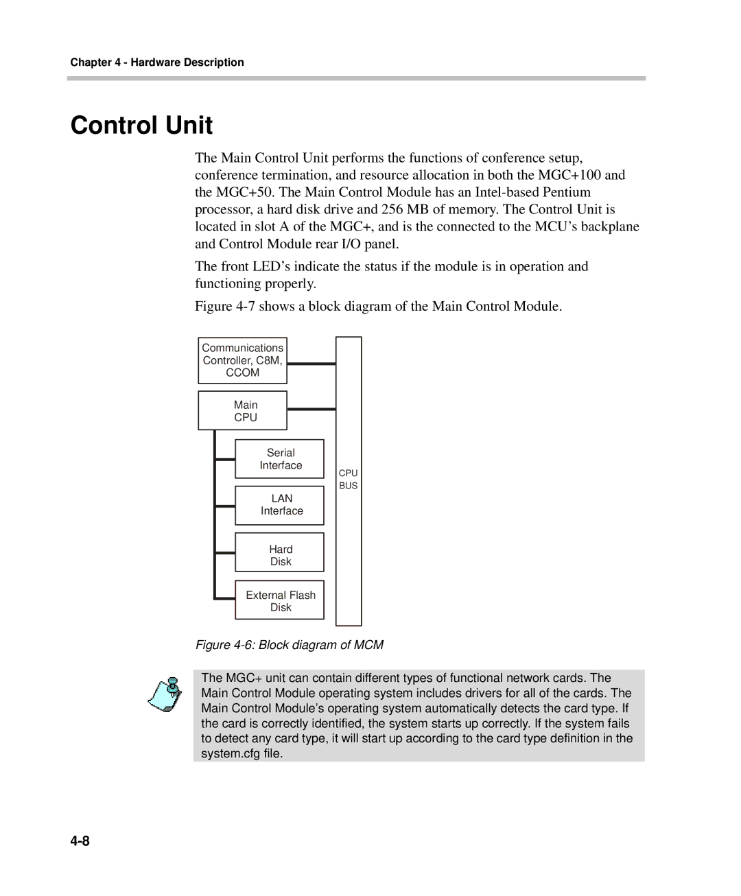
Figure 4-7 shows a block diagram of the Main Control Module.
Communications
Controller, C8M,
CCOM
Main
CPU
Serial
Interface
LAN
Interface
Hard
Disk
External Flash
Disk
CPU BUS
Figure 4-6: Block diagram of MCM
The MGC+ unit can contain different types of functional network cards. The Main Control Module operating system includes drivers for all of the cards. The Main Control Module’s operating system automatically detects the card type. If the card is correctly identified, the system starts up correctly. If the system fails to detect any card type, it will start up according to the card type definition in the system.cfg file.